Arduino based room controller

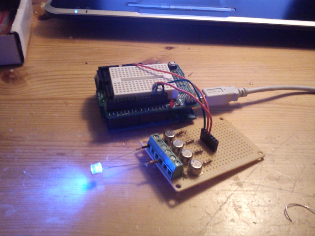
My ssr driver is working, at first the channel 4 was shorted/ON state always, but solved that:p

I am using it with out the pull up resistor!!! Is it needed? Maybe more stable?
Have notice it will interupt the sketch when the COM port is used, the PC are sending some shit in intervals,
Using the 5 volt regulated from the arduino, maybe a external supply will make it more stable.

IMG_20111208_195812.jpg
[
 
Pullup res may help with stability. Every time you start the serial monitor, the sketch restarts, same as unplugging/replugging the arduino.. The external supply may become necessary based on what you are driving.
 
Pullup res may help with stability. Every time you start the serial monitor, the sketch restarts, same as unplugging/replugging the arduino.. The external supply may become necessary based on what you are driving.

Got it working, going to order the sensors and some ssr.
 
I have done a lot of work on code.

I soldered all my leads to the protoscrew shield I got from adafruit.

I got the RTC working so matter what time of day the arduino powers up it will turn on the right devices and select the right temps for the time of day it is.

git://github.com/maer/Arduino-based-room-controller.git

The latest file is MCCAlpha, which will be changed to beta after tomorrow when I set up the sensors and blower.
 
Hey Maer, I'm looking at your code and you are busy updating it, I will have to wait a while I guess......:high-five:
 
code is staying the same for now, until I can spend more money on hardware. I ditched the distance sensor because that was more or less a gimmick from the start.

I have had some problems, they seem to be related to the powerswitchtail, when it kicks on it sometimes screws up the serial interface such that the Arduino needs to be reset so the serial monitor will start again. I would add a display but at this point I have only one device being controlled and I have only 4 digital pins left...

So my question is - I am afraid to hook the ground from the PST2 to the ground on the Arduino. In the instructions it says that this is the ground from the AC side and somehow I think that would be bad. Am I right or is the reason I am having problems because this is not connected?

Here is the Arduino installed on the wall with sensors running out. I bundles the wires together after I ran and dressed all the wires.

P1020959.JPG


This is the blower that is connected to the PST2 that is controlled by the Arduino:

P1020965.JPG
 
code is staying the same for now, until I can spend more money on hardware. I ditched the distance sensor because that was more or less a gimmick from the start.

I have had some problems, they seem to be related to the powerswitchtail, when it kicks on it sometimes screws up the serial interface such that the Arduino needs to be reset so the serial monitor will start again. I would add a display but at this point I have only one device being controlled and I have only 4 digital pins left...

So my question is - I am afraid to hook the ground from the PST2 to the ground on the Arduino. In the instructions it says that this is the ground from the AC side and somehow I think that would be bad. Am I right or is the reason I am having problems because this is not connected?

Here is the Arduino installed on the wall with sensors running out. I bundles the wires together after I ran and dressed all the wires.

This is the blower that is connected to the PST2 that is controlled by the Arduino:

I would not plug the Arduino into the ground of the PowerSwitch Tail.

Which PST do you have? The PST II's are working fine for me, without any loop back from the tail. I think that the II's not only handle more amps through them, but they also isolated the control circuit from the power.

Another thing to do is to run every thing on surge protector strips. Everything in my grow is on surge strips. We get a lot of storms here in the spring and power is up and down all the time.

One last thing is to ask if you are using pin 13 for anything?

I have the 2, the PST is plugged in to a power strip, the PC is running on a smart UPS.

Do you think I should try a diode / cap like OG13 did? Is the USB interface just unstable?
 
Hey Maer, I think you are seeing the same (or similar) "inductive kick" I was seeing. I separated the power supply to each part and it persisted. My grounds were all the same. This led me to believe it was due to the relays and the arduino being in the same enclosure, and was more an EMI type problem. I added the snubber circuit to absorb the "pulse" and it solved the problem. (the snubber is a resistor and capacitor in series across the relay output). The ground on the arduino should be shared with all 5 v powered components of your system--relay boards, displays, etc. Unless the PST has an input for ground next to the signal, I wouldn't connect them up. I will have to check my boards to see if ground is the same, it may not be a problem. If you use a backpack circuit board the LCD will only use 2 analog pins (share the I2C pins) i2c / SPI character LCD backpack ID: 292 - $10.00 : Adafruit Industries, Unique & fun DIY electronics and kits

I believe that if your serial monitor needs a reset, it means the arduino rebooted (you got the same thing I had). The fan motor has a larger inductive kick than a resistive load. Doesn't cause the reboot every time, just some time. If you cycle the fan on and off a couple time, I bet that you see the arduino reboot and the serial monitor freeze up on a fan off change.

I've been super busy w/ holiday stuff here, I will try to post the seed/sex box update tonight or tomorrow.
 
Is you distance sensor ultrasonic? You may get better response if you bounce it off an object rather than a water surface. (used to use them in an industrial application). Try a standpipe w/ a cork like object floating in the pipe. Hit the top with the sensor, will work a bunch better.
 
Is you distance sensor ultrasonic? You may get better response if you bounce it off an object rather than a water surface. (used to use them in an industrial application). Try a standpipe w/ a cork like object floating in the pipe. Hit the top with the sensor, will work a bunch better.

It is an infrared and it does work, just not worried about installing and programming it because it doesn't really serve a purpose. In later stages I will need it to sense the water level if I plan on refilling the res.
 
Alittle much for me. I'll wait till the movie comes out. It seems you are building a Master Controler unit? To much going on without any to do with dirt. I was never into electronics, and thats one place we all shouldve learned. GL,, Ill look back for some plant shots,,,,,,
Keepem Green
 
Hey Maer, the snubber would go inside the PST.....I'd be interested to see what's inside if you ever open it up. I would think they would have it inside already to protect the relay contacts. It goes across the relay output contacts--think of the relay as a light switch--the snubber is in parallel with the switch. It "dampens/snubs" the sudden change in current, and resulting arc across the relay contacts, when the switch opens.
 
Is your 5V dipping when the PST is on or off or changing state? A voltage drop to 3 volts would probably restart the arduino. Are you asking about adding a resistor between the arduino digital pin and the PST input? You could def try that easy.

In a snubber circuit like I use, the resistor by itself will defeat the function of the relay (switch)--it will act as a short circuit. The capacitor absorbs the energy, like a battery, it charges, the resistor slows the rate of charging. Think of the cap as a spring and the resistor as a shock absorber. They together smooth out the road bumps, if you are missing either, the ride will suffer.

so the digital pin outputs 5v and I need at least 3 to activate the PST so 220ohm will drop 5v to 3 and what sized cap do I use??
 
You can't use the cap on the output (only use the snubber across the relay contact). The resistor is just a stab in the dark for your setup. If it doesn't work, you may have to open up the PST.....

study the schematic for a cap.......two parallel lines. A capacitor is basically 2 plates insulated from each other. No current can flow (dc current that is) through a cap. You are trying the resistor only (like the shock absorber in the car suspension analogy)
 
Here's the schematic for the snubber detail.
snubber_schem.png


Note the resistor and capacitor in parallel with the relay contact. The fan motor is wired to 120 vac (hot lead) power thru the relay. The neutral lead returns to the plug. When the contact opens (fan off) the snubber absorbs the electrical pulse.

The driver side of the relay depends on what relay you are using. Some driver circuits use optoisolators to further isolate the arduino signal from the line power portions, although the relay provides the same function(most offer 4000 to 6000 volts of isolation).

Hope that helps Maer, was easier to draw it than explain it.....
 
Back
Top Bottom