Arduinos In The Grow Room: My Project

I ran into the same issue and never really solved it. The issue was the device would activate when the value exceeded the set point, but didn't de-activate when it dipped back to below the other set point. My next idea that I never acted upon was to add a boolean test that only activates the device when the test is true, but I went off on another tangent and never revisited the topic. I'm surprised I remembered this much.
 
I ran into the same issue and never really solved it. The issue was the device would activate when the value exceeded the set point, but didn't de-activate when it dipped back to below the other set point. My next idea that I never acted upon was to add a boolean test that only activates the device when the test is true, but I went off on another tangent and never revisited the topic. I'm surprised I remembered this much.


My switch lights, and watering pump code all works properly, so I should be able to figure out the math engine...

I just picked up 20 clones tonight (gifting is legal here) and my switch module is going to squeeze the trigger on the spritzer bottle for me for the next week or so, and I won't even have to take the dome off the cloner till then to check on them... I have it set for 5 squeezes every 10 minutes right now, will drop it as time goes by...

The more I automate, the more time I have to work on the automation :)
 
Which Peristaltic pumps were you using, do you remember, or have links?

Are the cheap ones any good? $10-$15 or best to invest in something more expensive?

I actually was thinking of a syringe, maybe driven by a servo... I think I could get pretty good accuracy with that. The problem then is keeping the syringe full... hmm...

These pumps deliver a specific volume per second, but depending on the voltage applied. How stable was your voltage? How did you power them?

If you don't remember, that's OK.... You have my curiosity piqued...

I bought Jebao units, a master and slave and hacked them apart on day one and tossed all the electronics and kept just the motors with clipon dosing pumps. TBH, the generics on ebay would work just as good. The trick is mapping the output to determine the multiplier. I ran into a problem of having the need of using a different multiplier depending on the requested dose. HERE is the code for just the dosers with Blynk. Obviously you can ditch the Blynk shit and take what ya need. I jacked the math of an Indian dude's YT video. I suppose you could map your multipliers too and keep them in an array or table and select the correct multiplier for your range of dose.

Though if you're going in soil, I don't understand your interest in peri pumps?
 
Though if you're going in soil, I don't understand your interest in peri pumps?


Automatic Watering isn't running right now, I only had a couple pumps, I need one pump and enough hose to reach the plant, for every plant. I currently have 30 plants. I have the auto watering working, reliably (that was a huge factor for me, NO LEAKS!) I ran it on a plant for the final testing, and it's ready to go... just need some $$$ :) My wife and I are both on Disability, so a very limited income...

The way it works is there can be multiple reservoirs, right now I'm using a 23L (5Gal) bucket, which is only enough to water at most, 10 times if I use 2L per watering. So just to water each plant once, I need 3 reservoirs. If I wanted to go away for a week, I'd need 5 or 6 reservoirs!

If I'm home, no problem, the system will notify me when the water gets low in a reservoir, and I can go refill it... A future project will be to bring in a hose from a faucet with a solenoid valve so I can automatically refill the reservoir when it gets low. That will likely be set up temporarily when I plan on being away, but it will take extensive testing and me certifying that the risk of water getting where it shouldn't be is as minimal as possible, and the risk acceptable.

Whether it fills automatically, or I do it by hand, I'll need to know how much water I add so I know how much of my liquid nutrients to add (Part A and Part B) Because each reservoir has an Ultrasonic Ranging sensor on top, pointing down at the waters surface, it can calculate how much water is added (to within a couple mL) and can therefore calculate how much nutrient to add, so why not let it add it automatically... This is where the Peristaltic Pump will be useful. I probably don't have to add a lot of code to make this work, just the calculations.

I only use Blynk as a window into the system, I can see things like temps etc, and can interact with sensors and modules, but ALL processing for the entire system takes place on the arduinos. I look at Blynk like a nice to have, but if it quit working tomorrow it's not the end of the world. I run a local server, so I don't rely on the internet being up, as long as my local WiFi is up, I'm in business. I do wish I could run the same app on more than one phone though.... Originally I tried writing my own app for my android phone, but I've never programmed with java, and while the syntax wasn't hard to pick up, the architecture of the software seems very complex, and trying to learn that, while still tring to keep writing Grow By Wire, still learning c++ and writing libraries etc... Along comes @Latitude17 and mentions Blynk. Well, I'm a roll your own type of programmer, rather spend forever writing my own code, than using someone elses, so I went and looked, having already decided it wasn't for me... I found excuses for a while, and struggled with trying to get an app working, and realizing "Hello World" was a long way from what I envisioned, and I still didn't know how to go to a new screen :( So I went ahead and grabbed Blynk for my phone, and built a little app that afternoon. I ended up installing the local server so the internet connection isn't an issue, and went crazy. I posted screenshots here in this thread as I was playing... I still keep modifying the app to meet my current needs, which mainly are debugging and testing, but I also use it so the system can send me a notification when a plant needs watering. It tells me which plant, and exactly where it is... I also get that info on the web page, but only if I'm looking. On my todo list is the ability to send a notification to my windows pc, just a console app that can notify me... I'm sitting here up to 20 hours a day sometimes...
 
I tried it your way first, to make a local arduino server and have it GET/PUSH data to/from my domain, but I was just too novice a coder to iron out the wrinkles and I just gave up the domain and and tried a few different automating platforms until I found Blynk. Blynk allowed me to completely forget about trying to learn networking code and libraries and all that jazz and focus on devices and making their libraries play nice(r).

Dosing pumps will be helpful for you to add your A and B. Depending how small of a dose you need of each is where the inaccuracy really stands out and is why I found the need to have several different multipliers when expecting output fluid to be really close to the desired # of ml. As the dose increased by 20ml, I would need to use the next calculated multiplier.

Solenoid valves will work great for soil plants and even drain to waste hydro, but because I run recirculating, I would need water to flow backwards once a week to access the waste line. I also wanted to keep all 8 dosing pumps as well as up to 4 Atlas Scientific probes held inline and the arduino was supposed to activate site reservoir pumps and push that res' nutes through the pipes past the probes and return to the original res for testing and calibrating the feed. That was when I used GH nutes. I now have the ability to control individual elements and a system like that would be badass.

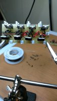
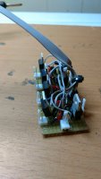
Any of THESE dosers will do what you want, just build multiples of the TIP120 circuits linked on my Dial-A-Dose github page to control each motor, and supply a 12V power supply sized to about a 1/2 amp per motor used. The TIP 120 circuit is easy to construct and solder. I used one sided SOLDERABLE BREADBOARD to lay out the circuits, and connected my power supply and leads to each motor as well as a DB9 connectors/cable to network to the arduino. For you, DB9 isn't needed. All you need is 1 Dpin each motor and a common ground.

circuit and motors.jpg diode.jpg IMG_20170207_192621976.jpg
 
Solenoid valves will work great for soil plants and even drain to waste hydro


I would only use these to fill my reservoirs if I had no other option, like I was away. I'm opposed to pressurized water lines in the grow room, we live on the upper floor of a mid size apartment building, so any flooding would be disastrous, and the obvious end of my grow... When I'm home, I'll keep them full by hand when the system tells me to :)

For watering the plants, I've taken every precaution I possibly can, there is no pressurized water other than when the pump is on, and the MAXIMUM water that could be lost is 5 gallons, and each grow area is capable of holding at least that much runoff in an emergency. I suppose nothing is 100%, but I worked really hard to be confident in this process...
 
What I meant by solenoid valve use was to have your one pump in your feeding res, and one solenoid valve for each plant and one open valve feeds it's plant while all the closed valves prevents feeding to those respective plants.

Edit - So you only have pump pressure when the code says so. The valves would just be used to determine where that pumped water lands, Plant A, B, C, D, E, F, G or H etc etc etc

Ah, I see... so rather than 30 pumps, maybe 3 pumps and 10 solenoids on each line, one for each plant?

I wonder which option is cheaper...
 
Ah, I see... so rather than 30 pumps, maybe 3 pumps and 10 solenoids on each line, one for each plant?

I wonder which option is cheaper...

It'll likely be contingent upon the amount of available D pins on your MCU.
 
It'll likely be contingent upon the amount of available D pins on your MCU.

54 :)

Either way, will need one pin per plant, either a solenoid, or a pump.
Using solenoids would require less tubing though if there was one feeder line with solenoids along the way
 
I think the most frustrating was the ESP8266, especially the one built into the Mega board. I had so many problems, it was rebooting all the time, nothing worked... It was so unreliable, I was going to give up on it and order some Ethernet shields. Of course, I eventually got it working, and now, I never have an issue with them, and they are extremely reliable...


I can't believe I just spent 4 hours trying to resolve this very issue, again!

I decided I wanted to try a new idea with my Sensor Modules. Rather than have the Mega 2560 orchestrate everything, I want to try having the esp8266 orchestrate, and the Mega will simply read sensors when the 8266 asks it to. For one, the esp has more memory, plus this will cut down DRASTICALLY the amount of data sent between the two modules.

I decided to rewrite it from scratch... I'm cutting and pasting some parts, like structs and variables, and am using the old code as my guideline or road map. I'm trying to make improvements where I see room to do so...

I then uploaded the code, and the esp8266 went crazy, rebooting constantly... Extremely frustrating, I was right back to when I was a rookie with these... and I was lost...

I have what I call blank sketches for all my boards, so in a case like this, I upload the blank sketch, and in the case of the 8266, it has WiFi code, and the OTA code as well, but that's it... It was fine, it connected to WiFi, and did not reboot...

I then installed my previous version of the Sensor Module code for the 8266, and it was rebooting too! WTH, this was working code???

Ok, back to the new version...
In the code that connects to the WiFi, it does a loop while checking to see if it is connected, and in this loop, there is a delay(1000). So, I decided to change it to a while millis() < startTime + 1000; instead. I'm not really sure where I picked this up, but it allows for finer control over delays, I can actually do something in the loop if I need to while waiting...

Now, when I was first playing with these ESP8266 modules, I had this problem a lot, and while it eventually went away, I never knew exactly why it had occurred...

Now I know... The ESP8266 has a built in Watchdog Timer, I knew this... and I knew this was what was causing the reboots... I just didn't realize HOW I had inadvertently fixed it...

The watchdog timer is there so that if your code gets into an infinite loop, the watchdog will reboot the module after, I think it's 2 seconds or something. My loop waiting for the WiFi connection looked like an infinite loop to the watchdog timer, so it kept rebooting. So the code needs a way to notify the watchdog timer that it's ok, we're still doing what we were designed for... and it is done in the Delay(x) method. Apparently a few things happen inside the delay method, but this is the one of interest now.

I discovered this as being the culprit when I first removed the loop altogether, and it worked fine... When I added the loop back, it rebooted.

I kept the new code for the delay, but I just added a delay(0); inside the loop. This is a delay for 0 milliseconds, so it really won't add any delay, but it will do it's internal work, including telling the watchdog timer to buzz off!

So while I could have simply cut and paste the old code in, I would not have actually learned the true cause.

Oh, why did the original Sensor Module code not work any more? It turns out that when I removed the delay and replaced it with the while loop, I decided to make that same change in the original code :( You know, pot and short term memory and all...


So the moral of this story is:
Always include a delay(x); in loops on the esp8266
even if x = 0


I'm curious why you want to use delay instead of millis?
 
I'm curious why you want to use delay instead of millis?

The watchdog timer is there so that if your code gets into an infinite loop, the watchdog will reboot the module after, I think it's 2 seconds or something. My loop waiting for the WiFi connection looked like an infinite loop to the watchdog timer, so it kept rebooting. So the code needs a way to notify the watchdog timer that it's ok, we're still doing what we were designed for... and it is done in the Delay(x) method. Apparently a few things happen inside the delay method, but this is the one of interest now.

Inside the delay method, the watchdog timer gets reset....
 
After more digging...

From: esp8266/Arduino

Within the delay method, it calls the esp_yield();method, which is where the timer gets reset. You could call esp_yield(); directly I suppose.

void delay(unsigned long ms) {
if(ms) {
os_timer_setfn(&delay_timer, (os_timer_func_t*) &delay_end, 0);
os_timer_arm(&delay_timer, ms, ONCE);
} else {
esp_schedule();
}
esp_yield();
if(ms) {
os_timer_disarm(&delay_timer);
}
}
 
Recent posts to my blog...

Click the titles to read more...

Friday, August 9, 2019
Night Watchman
A mysterious bug popped up while I was fiddling with code early tonight, suddenly it was going haywire when loading the list of sensors for a Sensor Module. I'm not sure the circumstances that kick off the error, but it had to do with me loading the sensor data in two parts because of a limitation of the MySql library (memory related)


Saturday, August 10, 2019
Down the rabbit hole!
Spent the day chasing bugs that weren't anywhere close to where I was looking :(


Sunday, August 11, 2019
More power part 2
I finally got the dc-dc converter installed, and also added a small green LED so I know when power is plugged in. The LED is powered off the 5v side of the converter, and has a 330 ohm current limiting resistor in series.

Monday, August 12, 2019
More Power, More Clutter...
If you look at the previous post, you'll see a nice neat and tidy board. I've added the dc/dc converter and the resistors for our transistors, and started adding the transistors, and it's starting to get messy!


Monday, August 12, 2019
We're gonna have fun tonight!
Probably the biggest weakness of the Sensor Module design is the amount of data being sent back and forth between the 8266 WiFi module and the 2560 MCU. While it is a hardware serial line and both systems share the same motherboard, overlapping data still occurs, and this messes up the XML structure.


Tuesday, August 13, 2019
We're gonna have fun for a few nights!
It's always nice when you get the opportunity to just completely rewrite something from scratch. That's not something that ever occurred in real life as a professional programmer :)
 
Recent posts


Wednesday, August 14, 2019
Do-Overs Rock!
At almost 60, I don't sleep a lot, so I spend my time working on Grow By Wire :)
I took a break, and was sitting here smoking a joint, and having a rum and egg nog (yeah, in August) in the middle of the night, with Metallica cranked to 100% in my ear buds...


Thursday, August 15, 2019
Are we having fun yet?
I sure am! :) If this wasn't fun, I wouldn't be doing it.
This complete rewrite of the Sensor Module has given me the freedom to not only fix bugs, but to do some major enhancements.


Thursday, August 15, 2019

Sensor Module Rewrite Update #1
If you've read my previous posts, you know I'm in the middle of a complete rewrite of the Sensor Module. This includes both the ESP8266 and Mega 2560 firmware. I'm also making a huge change in the way it works. The old version (V1) has the Mega 2560 orchestrating everything, and using the ESP8266 as a gateway to the database and WiFi,
This new version (V2) has the ESP8266 orchestrating everything, and only using the Mega 2560 to read sensors attached to it's pins.


Friday, August 16, 2019

Ever have one of those days?
I've been struggling all day with a problem in the new code.
 
Recent Blog Posts- click the title to read more...


Saturday, August 17, 2019
In an orderly fashion...
Things are looking pretty darn good right now (knock on wood!). I don't know how to describe it, but watching it run is like watching a precision military marching band whereas in the past, it was like watching recruits wearing clown shoes...


Saturday, August 17, 2019
An afternoon ramble...
When I embarked on this project, I was quite a rookie. Sure, I'd been a programmer for nearly 40 years, and that experience was invaluable, but not directly useful.


Sunday, August 18, 2019
Effortless Clones - finally!
I honestly think this is the ultimate cloning method. Last year, after years of very successful cloning using peat pellets, a humidity dome, and a spray bottle, disaster struck, and I couldn't get clones to root no matter what I did.


Monday, August 19, 2019
The "Mega Shield" Part 3
Link to Part 2
A complete rewrite of the Sensor Module firmware deserves a hardware upgrade as well doesn't it?
Introducing the "Sensor Module Backpack" AKA "The Mega Shield"

SensorModuleBackpack.png
 
Back
Top Bottom