DIY Carbon High Flo Filter - 30 bucks

MisterPeabody

New Member
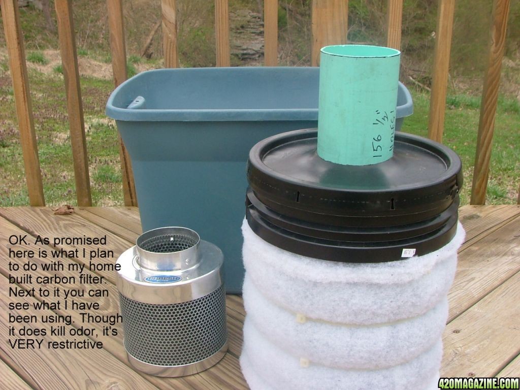
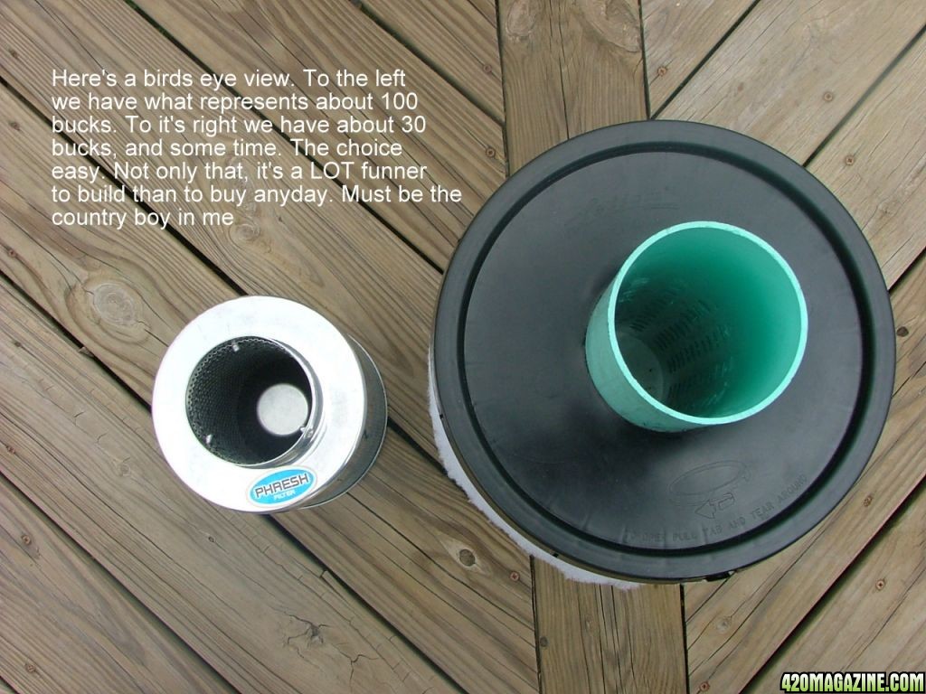
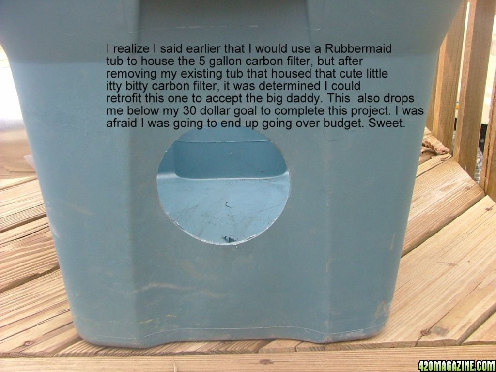
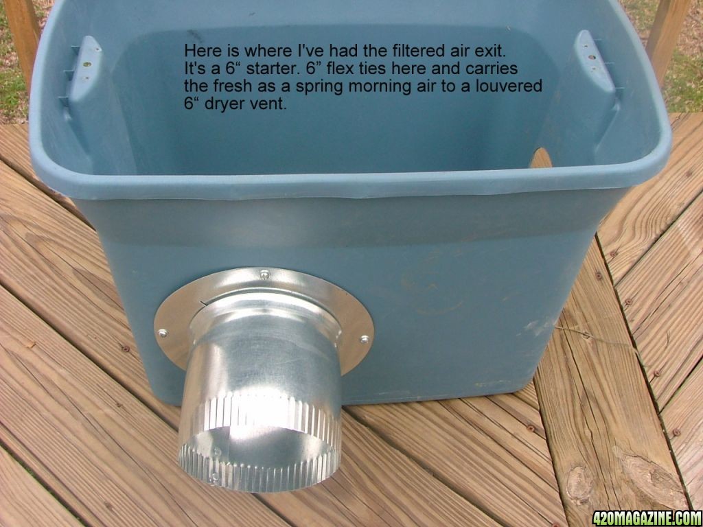
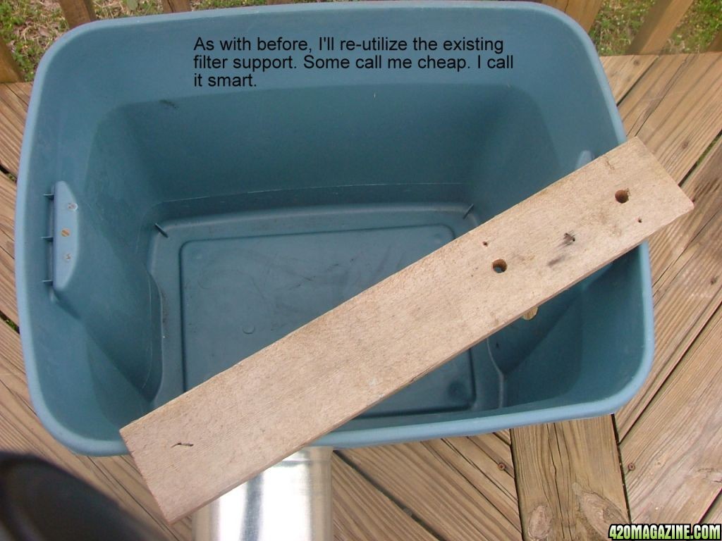
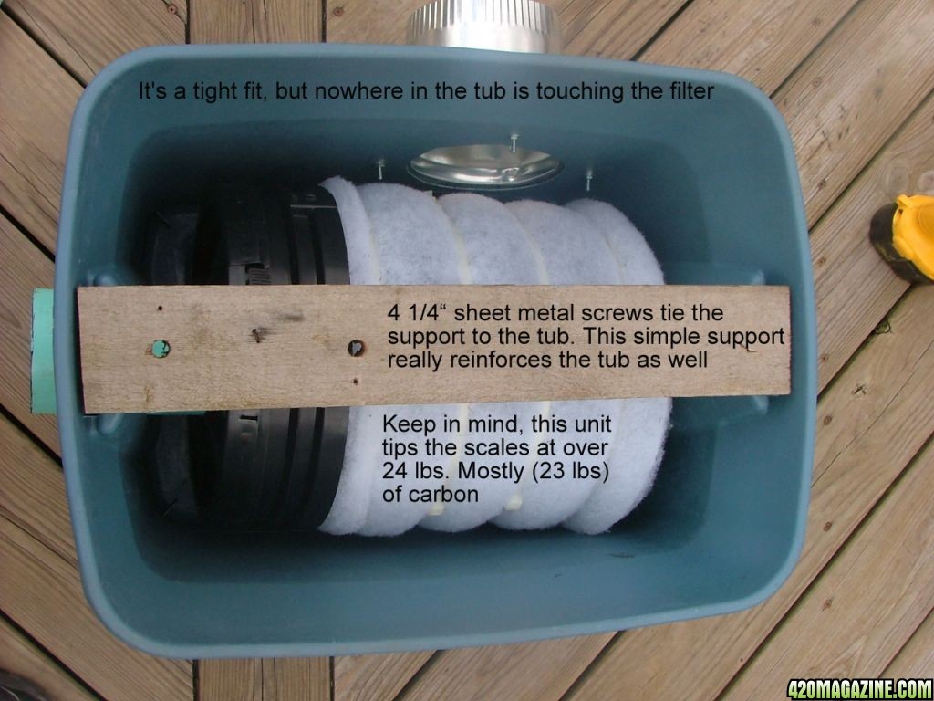
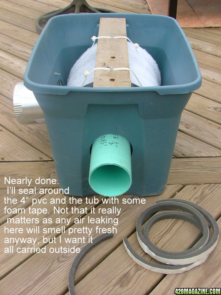
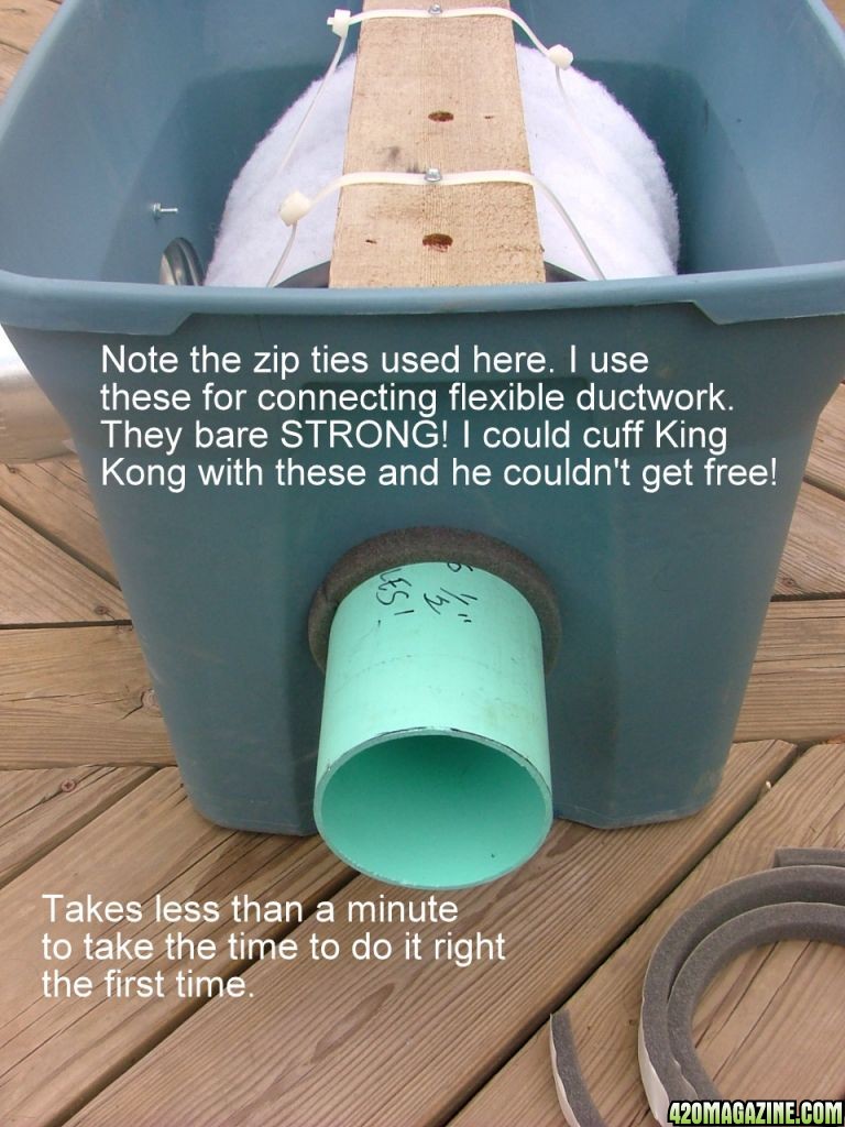
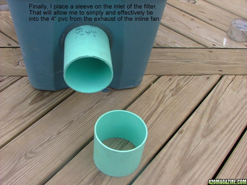
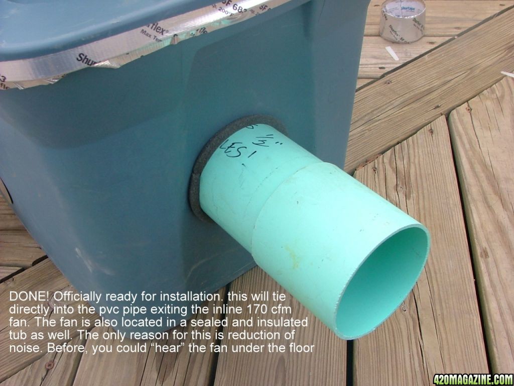
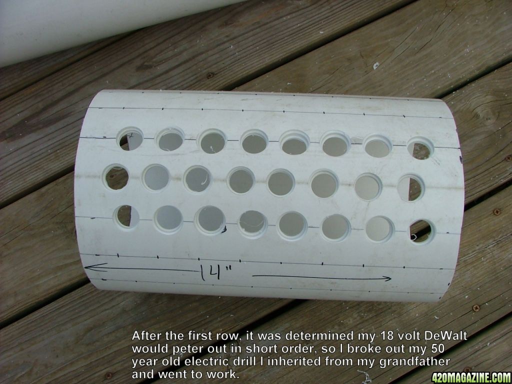
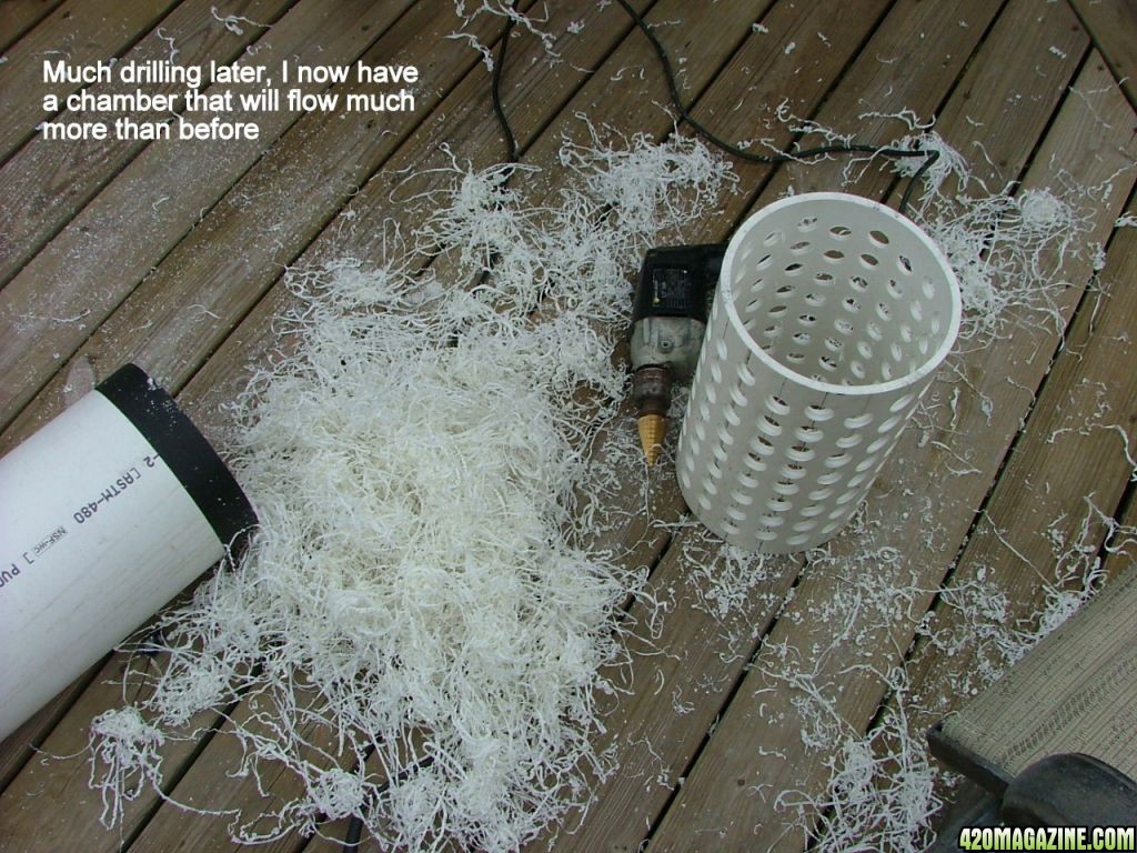
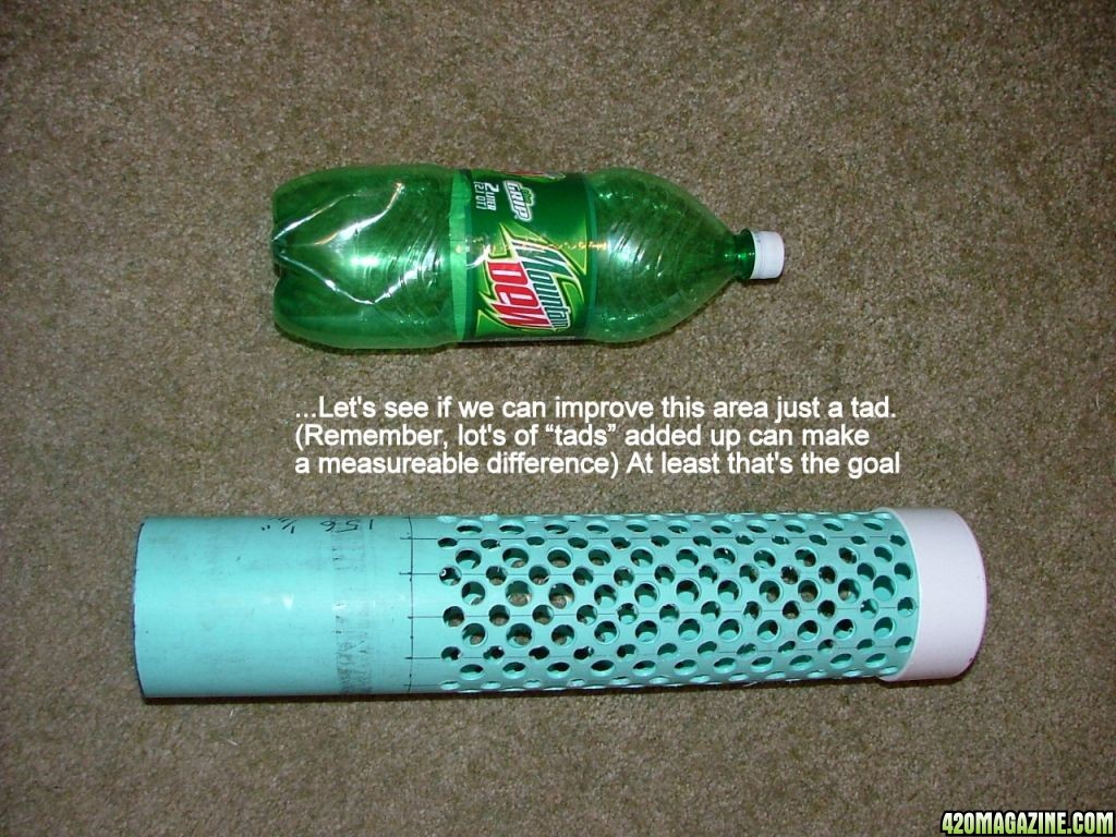
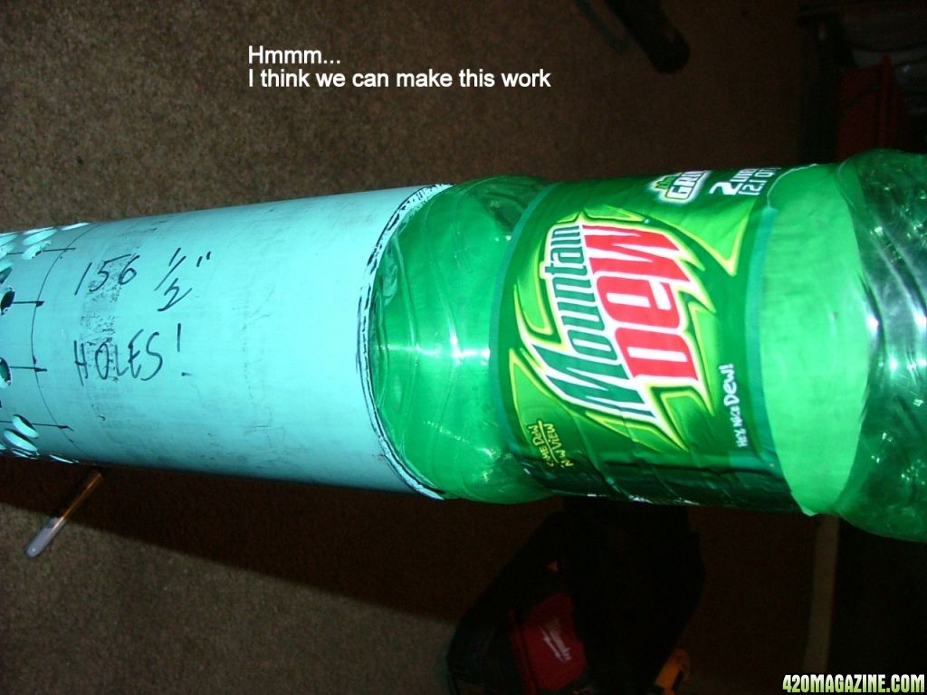
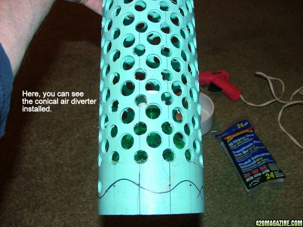
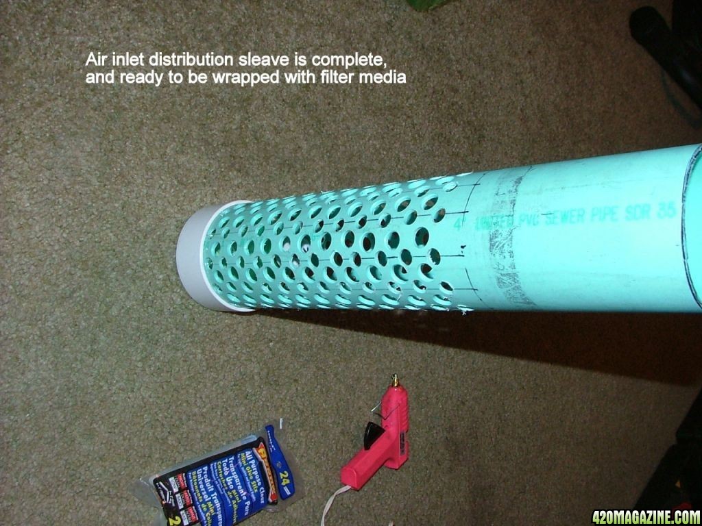
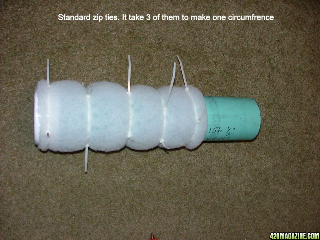
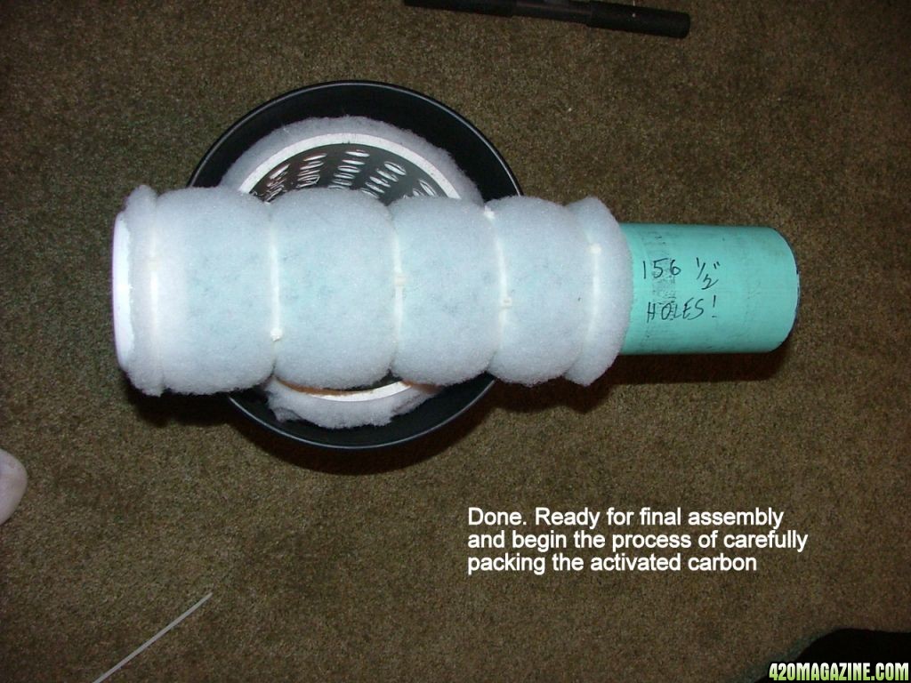
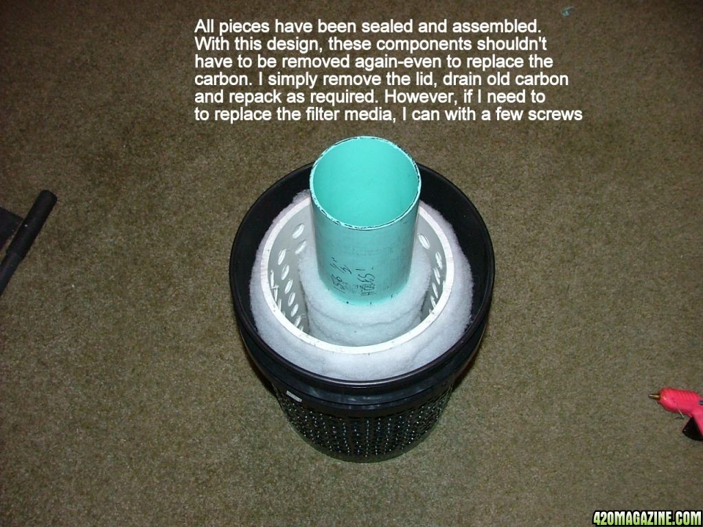
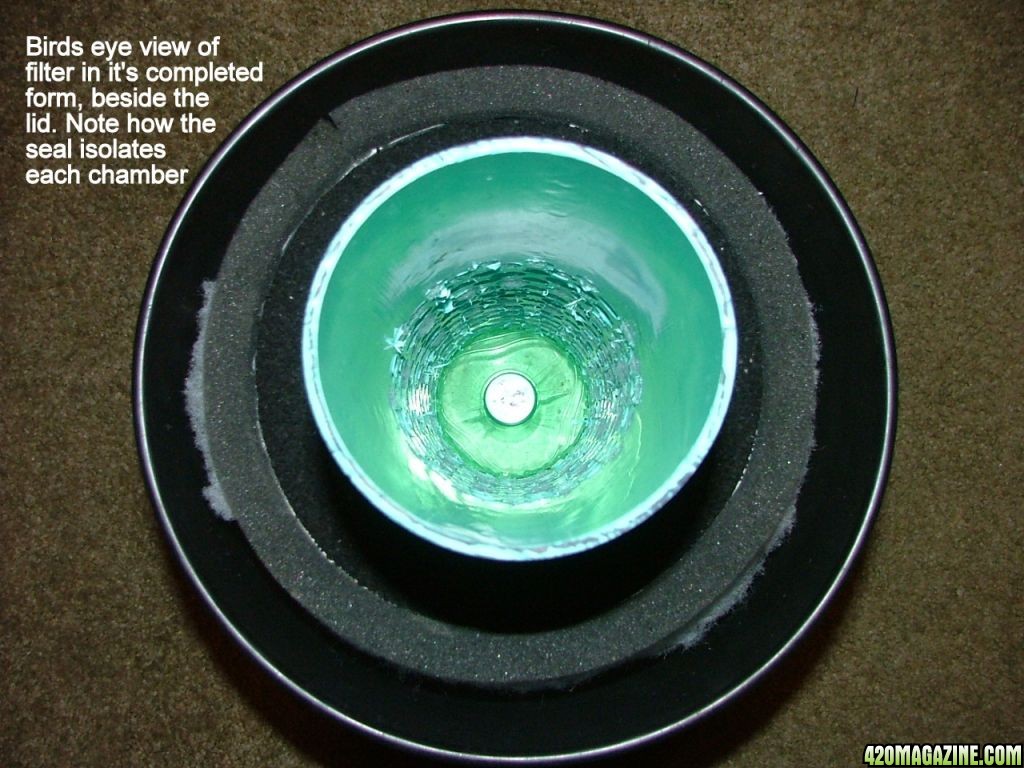
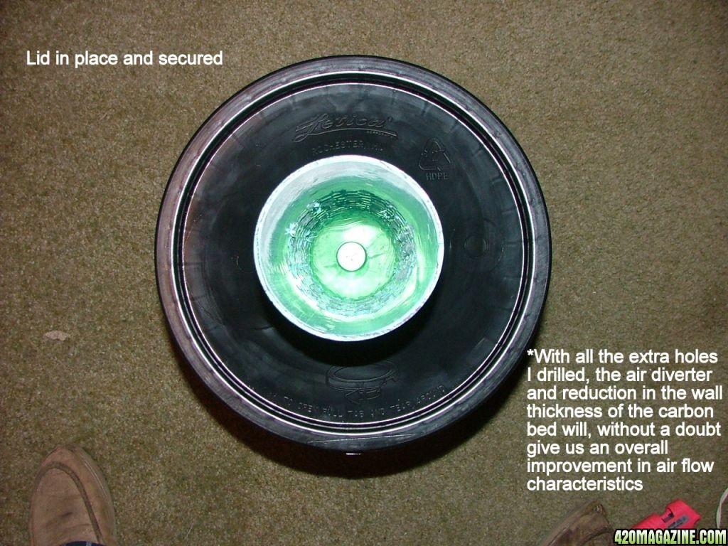
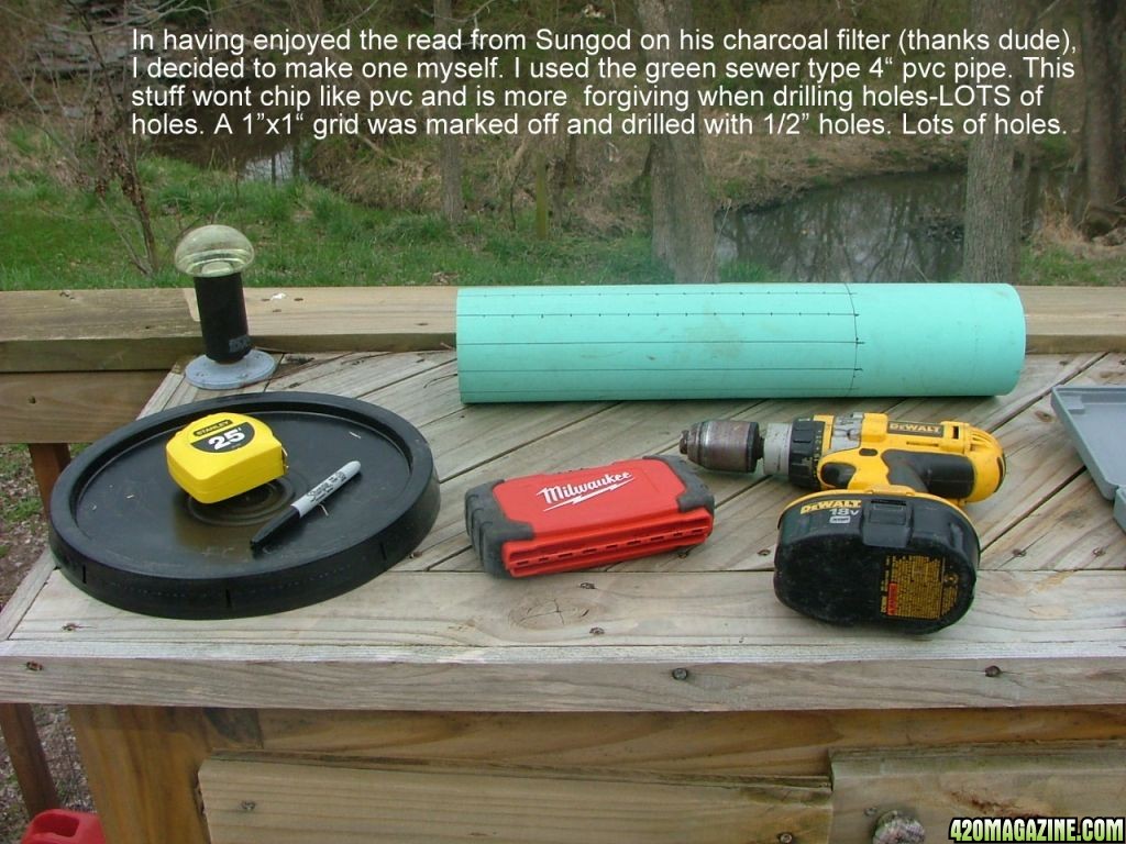
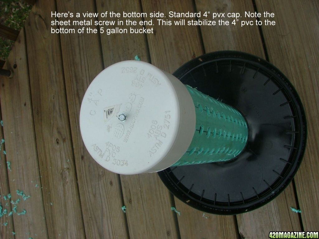
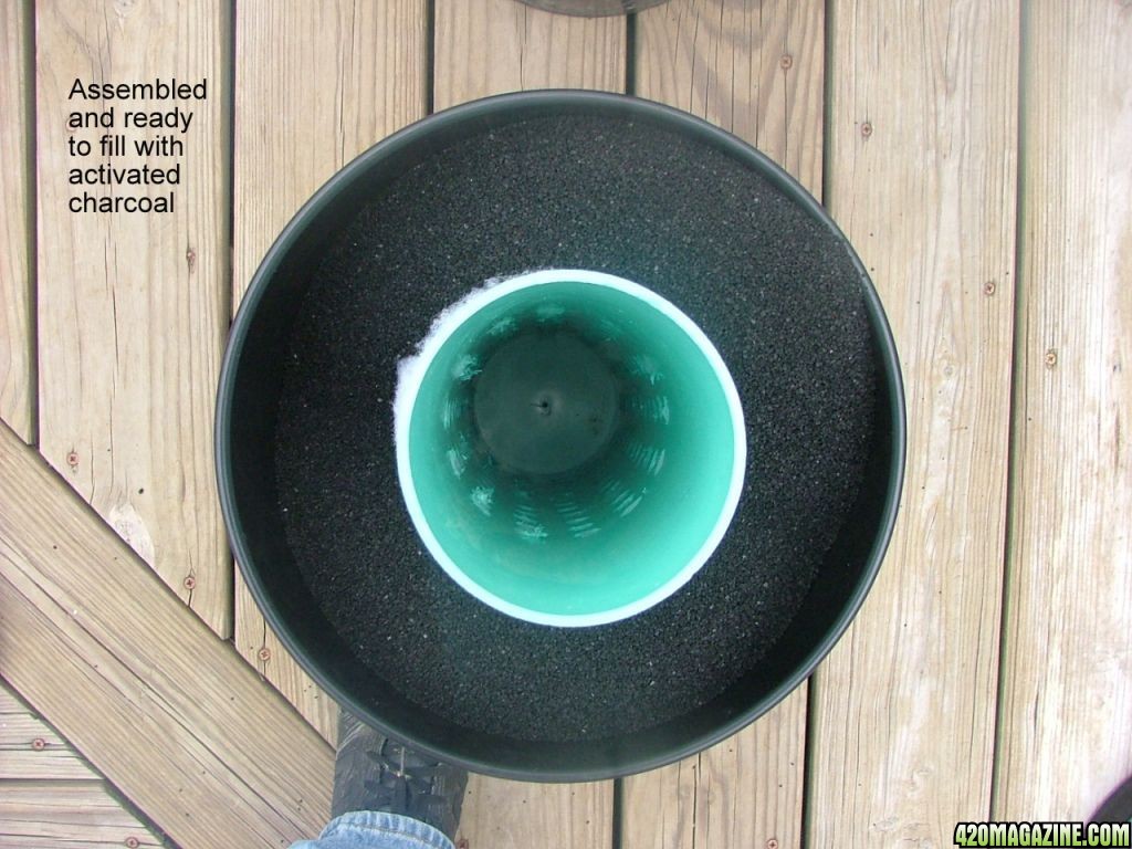
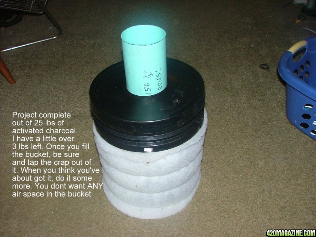
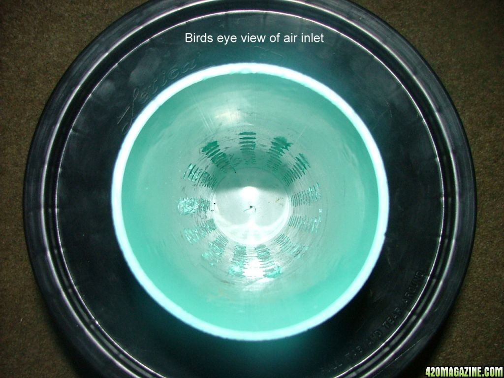
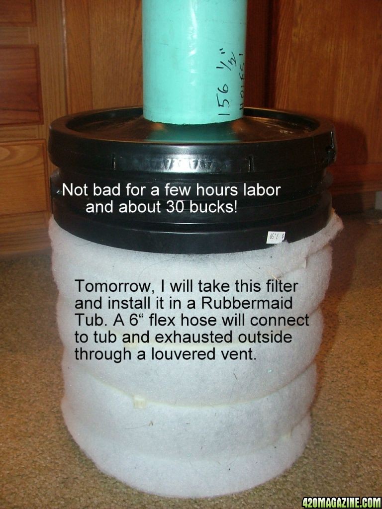
First, thanks have to go out to Sungod. As soon as I seen his, I knew I could do something with this design. My cab is for the most part a passive cabinet. I'm constantly pulling air through it. There are 3 passive air inlets, and the way it's designed, blower and filtering device are both located outside of cabinet. With this design of filter, I can place the completed filter inside a Rubbermaid tub. Cut one 4" hole in the end of tub and place the 4" pvc pipe through the hole in the tub. This is where the exhaust of the inline turbine fan goes into. In the side of the tub I'll place a 6" galvanized starter secured with stove bolts. The 6" flex connects here and goes outside through a louvered flap type dryer vent, blowing garden fresh carbon killed air! Enjoy!:thumb:

1907.jpg


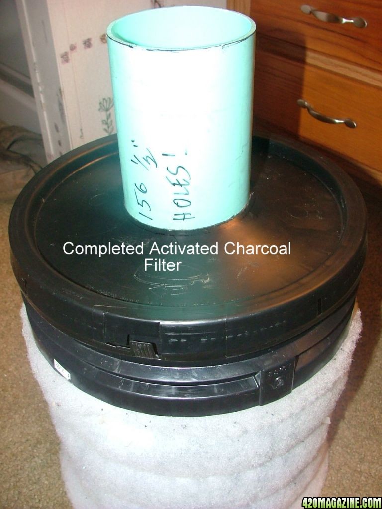
When I get it in it's final resting place, I take a few pics. This baby puts that factory built, 4" diameter tinker toy wanna be a real carbon filter to shame! I Love this place! You guys have posted so many ideas I have utilized, and in some cases was even able to improve upon. That's what it's all about and why I LOVE 420. :peacetwo:
 
Ok. As promised here's the rest of the install. I got in installed this afternoon. I didn't question whether it would work-I didn't know how much less restrictive it would be, and if so, it should have increased the rpm of the inline fan, thus increasing the airflow, thus reducing cab temps. All of the above held true. I've never been able to keep the cab under 82deg at the hottest past of the lights on, but I have been able to drop the cab temp by 1.7 deg! That might not sound like much, but I'll take it anyday! Also, no stinky. Someone posted on another thread IF these homemade filter will work. Damn right they do. I'd put this one up against my pre-built carbon filter anyday. I'll bet this one will last a long spell as well.:yahoo:

17102.jpg

18100.jpg

1956.jpg

2054.jpg

21129.jpg

22115.jpg

23106.jpg

24100.jpg

2732.jpg

2829.jpg


(Overlook the typos. Us country boys cant type fer shit)

This was a fun project. Hope you enjoyed it as much as I did.:peacetwo:
 
Great thread and love the Mc Gyvering ! That's a great idea that I just might need to put to use in a few weeks...Thanks again + rep !
 
Awesome! +reps
What carbon did you use?
I would love to hear and see more about your fan in a tub.

edit: can't +reps you yet, need to spread the love.
 
Nice!! and on a tight @ss budget. Im impressed.

Q: besides the smell aspect of venting, can technology stuffed choppers detect anything else than makes it through the matrix of the carbon?
 
Awesome! +reps
What carbon did you use?
I would love to hear and see more about your fan in a tub.

edit: can't +reps you yet, need to spread the love.

The carbon I got from a landscaping store. They have many waterfall like displays, and use this for their water filtering as well. I purchased a five gallon bucket full, and it tipped the scales at a little over 26 lbs. I paid right at a buck a pound.

As I said earlier, this has reduced my cab temps, and is without a doubt an improvement over the factory unit.

This being said, and in my quest for more power, more efficient, cooler, ect., or the fact I'm just anal retentive and can't help it, I decided to dissect my factory carbon filter element, just to "see" how the pros do it. From what I've seen, my design leaves room for further improvement. Yea, I know, leave well enough alone BUT if ya CAN improve something, why not?

OK. Here is what I've found, and soon to implement into the above project. When I took the factory Phresh Carbon filter apart, the first thing I wanted to see was how thick the bed of carbon was, and was it a single bed, or several beds. (Amazing how simple they are). They have a single bed that the circumference of being about an inch thick. Keep in mind ALL air has to pass through this bed of tightly packed carbon, BUT IT HAS TO FLOW THROUGH IT. My bed is about 4.5" thick in circumference. That spells restriction in my ever so humble opinion. SO....I'm going to create another air chamber using a section of 8" PVC. Figuring in the packed thickness of the filter media, then the carbon packed into the void should give me a bed of carbon, full length as before, packed tighter than a hatband, but only between 1.5" and 2" circumference of carbon. Theoretically, this should reduce restriction through the carbon bed by 50% or so, and still give me better filtering ability than factory. I'm going to insert something conical shaped into the bottom of the 4" PVC pipe, as this should tend to "direct" the air through the bed with less restriction. The factory Phresh Filter feels the need to add one, so presumably they've done more research than me, and in theory, it holds water. I'm also gonna pop another hole in the middle of the grid pattern in the 4" PVC, and on the bucket as well. Even though my holes are larger than the factory unit, they have more holes per sq. in. so I'm gonna give it all I can.

As usual, I'll try and snap a few pictures, and will post any improvements.:roorrip:
 
Nice!! and on a tight @ss budget. Im impressed.

Q: besides the smell aspect of venting, can technology stuffed choppers detect anything else than makes it through the matrix of the carbon?

They Do have other technology. Google "FLIR camera" It stands for "Forward Looking Infrared". It basically picks up a radiant (infrared) heat signature. I designed my cab like a Faraday Cage and used Mylar with the reflective side out on the inside of the cab before insulating it. In theory, the heat signature is hidden or at least reduced to that of a normal household appliance.

Fortunately, where I live, the local police dept. has recently had to sell both their choppers and let go 3 of the pilots that our tax dollars paid to sit on standby for those "just so" emergencies. MAJOR cutbacks on police, fire and other emergency related expenses. So I guess there is always a silver lining to every dark cloud....hehe.:yahoo:
 
Smart cookie, does everyone follow this mentality.

When you say you deploy a Faraday cage, does this just mean your casing is grounded blocking any electrical field detection of your running gear?

So given the aspect you just informed me on, your still creating a focal heat source correct.

Half your luck on the departmental cutbacks, at least from that perspective anyways

Electromagnetic shielding was the goal, and to prevent any entry or escape of an electromagnet field, be it send or receive. Whether or not it would be of any use (other than a large EMP wave from overhead), or whether there is indeed equipment utilizing this technology is up in the air, though I have heard rumors. As far as grounding, the cab is grounded to a 6' piece of rebar driven into the ground to a depth of 5', respectively. Other things like my house is grounded here as well. The theory is if my cab is like a capacitor, I have this capacitor shorted to ground.

A focal point of heat source? To an extent that cant be argued, however, with the interior lined with mylar then with 2" duct wrap surrounding all 6 corners. This is followed by that diamond plate light diffuser growroom liner and the cabinet exchanging the air numerous times per minute, most of the heat source is carried out of the cab in short order. I'm hoping it resembles a dryer vent (it really is).:peace:
 
No matter how you look at it, prevention is worth its weight in gold.
Kudos for taking the time & having a proactive stance.
Make sure you point me in the direction to your build, that way i can delve into how you built it more.


exchanging the air numerous times per minute, most of the heat source is carried out of the cab in short order
That was what i was referring to in saying a focal point heat source.
We dont have dryer vents here, however i can imagine what they look like.

I was thinking maybe its possible to add an extra container before venting to atmosphere, deploying a cheap water spray bar that sprays a canopy of straw of something. Cheap still to deploy, & Positive pressure venting would still occur given continuation of ducting. Just thinking out loud anyways in regards to assisting a potential drop in temp.

On the flip side, do you use CO2 edition?> How do people go about venting & hence throwing money down the drain with that frequency if its being extracted?
 
No matter how you look at it, prevention is worth its weight in gold.
Kudos for taking the time & having a proactive stance.
Make sure you point me in the direction to your build, that way i can delve into how you built it more.


That was what i was referring to in saying a focal point heat source.
We dont have dryer vents here, however i can imagine what they look like.

I was thinking maybe its possible to add an extra container before venting to atmosphere, deploying a cheap water spray bar that sprays a canopy of straw of something. Cheap still to deploy, & Positive pressure venting would still occur given continuation of ducting. Just thinking out loud anyways in regards to assisting a potential drop in temp.

On the flip side, do you use CO2 edition?> How do people go about venting & hence throwing money down the drain with that frequency if its being extracted?

Your a sharp cookie. Think outside the box. My only concern, would be the heat signature following the 6" duct leading outside. I have considered running the exhaust through a small swamp cooler, cooling the air exiting the dryer vent. There I go again-trying to think myself INTO a box..hehe.

As far as C02 is concerned, in this environment, it would be a moot issue. Far too many cab air exchanges to even consider C02 injection. :cool:
 
Well, the first thing I found out was 8" PVC isn't an easy animal to find. Once I did, I realized that for the 14" I needed, I couldn't justify the purchase as it comes in 20 ft sections. Hell, I couldn't even transport it in my PU truck. Before I had the opportunity to even ask the price, the guy told me to hang on and put me on hold. When he got back on the phone he said he had a 7' section. I asked how much? Come get it was the reply. Half an hr later I have a 7' section of 8" schedule 40 PVC pipe. The best part? FREE!!!! I did purchase an 8" cap for it. I figured I'd have to go over my 30 dollar budget, and I did. Total cost now? $36.43. So now, thus far, I'll have to call it the "Under 40 Dollar Carbon Filter"...:popcorn:
 
Just so im on the level, this new section of pipe, is to achieve the below?

Theoretically, this should reduce restriction through the carbon bed by 50%
 
Just so im on the level, this new section of pipe, is to achieve the below?

The new section of pipe will create a chamber that has less volume of activated carbon (around 1.5-2.0 inches as apposed to the 4.5 inches it required before. Yes, less carbon, but I had it so thick I'm thinking it restricted the airflow more than necessary. I'll post some photos. They say a picture is worth a thousand words...:bong:
 
LOL, thats gold.
6284.jpg


Reminds me of a line from The Mummy.
"what's a place like me, doing in a girl like this"

Bud, well done. sh^t load of effort drilling & re-tracing some old steps, but your certainly got there dude.

First things first though,
Pointing_Smiley_by_thejagman22.gif
that WAS your cute pink glue gun, just admit it..lol


when you sealed the outer breather ring, is the material flush under the lid?

Ok. I cannot tell a lie. I bought the above pink glue gun for my wife when she felt the need to glue eyeballs onto goofy Styrofoam shaped into crude heads. And yes, that fad was short lived, and that cute little pink glue gun has resided in my goody box for around 8 years. And yes, there are many other "Manley Projects" I have used it on. So you caught me...Cheers! LOL.. :popcorn:
As far as the material being "flush" with the lid. Sort of. If anything, it's slightly extruded against the lid. I almost thought I was going to have to jump on it to get the lid to seal it. If you shake it, not really much of anything happens. It's packed pretty tight. I didn't photo it when I was in the process of filling the carbon, but I took a 3/8" Lexan rod to pack the carbon while chopping the sides to get it to all settle in and fill all the 1/2" holes drilled into the 4" PVC. I probably spent 15 minutes of so just packing and settling in the carbon.

I got it all hooked up this morning, and I picked up a reduction of almost 1.5 deg performing this rework (1.2-1.4 degrees). It may not sound like much, but I'll take it. This project has been eerily familiar to my days of 1/4 mile drag racing. The shit I would go through just to pick up 1/10th of a second through the quarter mile. I must be insane:cheer::peacetwo:
 
so down 1.5deg at the cabinet sensor im assuming, or do you have an inline probe? . Its still a gain regardless, & yes, talking strip mentalities, then every shaving you should be happy with by default.

I was kinda expecting an cf airflow increase estimate though bud


Once again, wrong place, ......wrong place.
Ive sooo got to stop talking to Americans, - i cant just say "we've got to organise a get together for a BBQ & Brew, whilst the women talk their sh^t, we can talk design"

To give you anything other than a real crude estimate would entail the use of a velometer, which incedently, I have inquired about through a friend who's firm he represents happens to have one. If I can get my grubs on it for an evening, I'll post a no load calculation of airflow, and one with the carbon filter installed, as well as a comparison using the factory Phresh vs Homebuilt version. That would be an interesting shoot out. THOSE figures I will post. I don't want to make false claims, but if you want a guess I'll give it to ya. Id say with the factory 4" Phresh filter installed, there was around a 30%-35% reduction with the reostat on the speed controller bypassed and the unit receiving full line voltage. I'd say I'm maybe a 15% reduction in cfm with the homebuilt filter in the same conditions. Now, figures such as cab temps can easily be managed. The temp probe I use is a digital unit with the probe located at the plant canopy. I formed a small radiant shield above it to prevent the probe from picking up radiant heat and more focus on air temp
:roorrip:
 
Back
Top Bottom