

Very cool setup otter!
Navigation
Install the app
How to install the app on iOS
How To Use Progressive Web App aka PWA On 420 Magazine Forum
Note: This feature may not be available in some browsers.
More options
You are using an out of date browser. It may not display this or other websites correctly.
You should upgrade or use an alternative browser.
You should upgrade or use an alternative browser.
Out Of The Tent Extraction Setup
- Thread starter StoneOtter
- Start date
- Thread starter
- #22
Thank you sir.Very cool setup otter!
- Thread starter
- #23
The bypass is something I have to do here next for the next one. It's an outside exhaust and winter is here soon. Some weeks it's going to be too cold and I'll want to put it inside.Otter, this is excellent!
Love the "muffler" idea, and really there is only one connection point where the seal is absolutely critical: the exhaust side connection to the filter. Everything else is either filtered air or clean air, really.
A leak anywhere else, and it is either sucking fresh air in, or pushing cleaned air out after the fan.
I'm highly considering this idea to run multiple tents. Not 100% sure yet, but it's definitely a better option than running 2 fans/filters. I may even bump up to an 8" fan/filter, but probably not right away.
Even better is the filter could be bypassed for the early stages where it's not an issue.
- Thread starter
- #24
Enjoy DankmanI'll be copying this! Thanks SO
The bypass is something I have to do here next for the next one. It's an outside exhaust and winter is here soon. Some weeks it's going to be too cold and I'll want to put it inside.
Excellent.
")
I put my fan order on hold. Thankfully it hadn't shipped yet. The one thing I hadn't looked at on those fans was...
static pressure.
duh duh duuhhhhhhhhh.... /scary music
Dang it, dang it, dang it. Those were excellent fans, but at a 60Pa per fan (compared to a 300Pa on my 6" duct fan), well, I think it's probably safe to say those weren't meant to pull through any type of filter.
I have two options at the moment:
a) run a single 8" duct fan
b) run two 6" fans in parallel
I came up with the cmf needed to exchange the air once every 60 seconds. That was taking the total volume (4x8x7) then adding 40% to account for filters, duct work, etc. That give me 313.6, we'll call it 320 for easy math.
With the 8", it's rated max is 740cfm with a Pa of 745. That's ~2.3x the needed airflow capability, so would obviously be running it on one of the lower settings. (2 or 4 out of 10 possible.)
Or I could run two 6" in parallel instead, and run them on a med-low setting (3-5 / 10.) This isn't a bad deal, as it would allow for redundancy in case of failure.
Finally, I could just run a single 6" on the upper end of its settings (7-9 / 10.)
8": 140w | 740cfm | 745Pa | 39dB |10-speed
6": 40w | 350cfm | 300Pa | 32dB | 10-speed
- Thread starter
- #26
Choices are hard some days. What's important about each method to you? How will it help you the best?Excellent.
I put my fan order on hold. Thankfully it hadn't shipped yet. The one thing I hadn't looked at on those fans was...
static pressure.
duh duh duuhhhhhhhhh.... /scary music
Dang it, dang it, dang it. Those were excellent fans, but at a 60Pa per fan (compared to a 300Pa on my 6" duct fan), well, I think it's probably safe to say those weren't meant to pull through any type of filter.
I have two options at the moment:
a) run a single 8" duct fan
b) run two 6" fans in parallel
I came up with the cmf needed to exchange the air once every 60 seconds. That was taking the total volume (4x8x7) then adding 40% to account for filters, duct work, etc. That give me 313.6, we'll call it 320 for easy math.
With the 8", it's rated max is 740cfm with a Pa of 745. That's ~2.3x the needed airflow capability, so would obviously be running it on one of the lower settings. (2 or 4 out of 10 possible.)
Or I could run two 6" in parallel instead, and run them on a med-low setting (3-5 / 10.) This isn't a bad deal, as it would allow for redundancy in case of failure.
Finally, I could just run a single 6" on the upper end of its settings (7-9 / 10.)
8": 140w | 740cfm | 745Pa | 39dB |10-speed
6": 40w | 350cfm | 300Pa | 32dB | 10-speed
Choices are hard some days. What's important about each method to you? How will it help you the best?
Those are good questions.
Most important? It works.
Seriously though, I'm not really married to either fan setup. I am set on the box concept though. I see pros and cons to all.
The single 6" would work, but I'm going to be running that fan close to max. To me that means more wear/tear, and probably a little shorter lifespan. (But maybe not.)
The dual 6" would be alright. I could run on lower speeds, and at times can probably just run a single fan (when bypassing the carbon filter, for example.) What I'm not 100% sure on with that is how two fans pulling from a single point (the filter) would work out. Would one pull harder than the other? If so, would that put undue stress on the fan that is working harder? (I think this is probably negligible in this type of application.)
The single 8" would also be fine. But in times where the filter is bypassed, what would be the minimum cfm it would draw? An advantage to this would be that if I were to end up venting 3 spaces down the road, I could. (Which I doubt, but I could also use a third input to suck air from the room itself in a pinch if needed.)
I'm going to see if the manufacturer has any input, and go from there I think.
So much for the chat feature on their website. 
Didn't tell me anything that I didn't already know.
I think either the dual 6" or single 8" would end up best. The pair of 6's would eat less juice, even on max, but the 8" wouldn't run past 50% I'm guessing. Which if the 10 speeds are actually percentage of operation (10%-100%) then 50% would be 70w and 370cfm. 40% would be 290cfm and 56w. (In theory.)
The two 6" running at 50% gets tricky. In theory it should be moving a combined total of about 350cfm, at 40w, but the math isn't quite true to those numbers when running in parallel. It's close though, so whatever.
I could just simplify and run 2 6", with a filter attached to each one. That simplifies the spread of the load. Along that line, I could also just make it dual chamber, and one fan runs one tent, the other runs the other one. That would make bypassing interesting though.
(Sorry I'm trainwrecking your thread. Just trying to get my head around it all.)
- Thread starter
- #29
This is the place to do that. No worries, I like a good trainwreck and can learn from your thoughts. I haven't made the 4 x 4 one yet. Maybe there's another way for me to look at it.So much for the chat feature on their website.
Didn't tell me anything that I didn't already know.
I think either the dual 6" or single 8" would end up best. The pair of 6's would eat less juice, even on max, but the 8" wouldn't run past 50% I'm guessing. Which if the 10 speeds are actually percentage of operation (10%-100%) then 50% would be 70w and 370cfm. 40% would be 290cfm and 56w. (In theory.)
The two 6" running at 50% gets tricky. In theory it should be moving a combined total of about 350cfm, at 40w, but the math isn't quite true to those numbers when running in parallel. It's close though, so whatever.
I could just simplify and run 2 6", with a filter attached to each one. That simplifies the spread of the load. Along that line, I could also just make it dual chamber, and one fan runs one tent, the other runs the other one. That would make bypassing interesting though.
(Sorry I'm trainwrecking your thread. Just trying to get my head around it all.)
My biggest concern is not having enough flow.
I think the bare minimum cfm is going to be around 120 total, coming out of the fan. (224 ft^3 / 3min = ~75, rounded up to 80. Add 20cfm for filter, 8 for other resistance, and rounded up to 120 to be safe.)
At 120cfm, that turns the tent over once every 3 minutes. I'd like to cut that down to every 2 minutes as my own minimum, preferably a little quicker.
Air turnover once every:
- 3 min: 120cfm (bare minimum)
- 2 min: 180cfm
-1.5 min: 240cfm
-1 min: 360cfm
-30 sec: 720cfm
I would like to keep the air exchange to full replacement every 60-90 seconds, so 240-360 would be the normal range. Being able to adjust from there would be nice.
With a single 6" fan, that's going to put it right on the edge of its max rated cfm.
First things first, I think the right idea is to use two 6" filters.
Second is to separate those filters mechanically, so each supply line is run through its own filter.
Finally, we're back down to the fan setup.
For that, I think running 2 fans is the better option. Now the question is whether or not to isolate the fans?
I also have a 4" fan and filter that I could use as the second fan if I isolate. Runs 205cfm, which for a 4x4 is just enough with a filter to turn it over about once every 60-90 seconds.
Ugh... damn me and my silly ideas!
- Thread starter
- #31
What do you mean by isolate the fans?My biggest concern is not having enough flow.
I think the bare minimum cfm is going to be around 120 total, coming out of the fan. (224 ft^3 / 3min = ~75, rounded up to 80. Add 20cfm for filter, 8 for other resistance, and rounded up to 120 to be safe.)
At 120cfm, that turns the tent over once every 3 minutes. I'd like to cut that down to every 2 minutes as my own minimum, preferably a little quicker.
Air turnover once every:
- 3 min: 120cfm (bare minimum)
- 2 min: 180cfm
-1.5 min: 240cfm
-1 min: 360cfm
-30 sec: 720cfm
I would like to keep the air exchange to full replacement every 60-90 seconds, so 240-360 would be the normal range. Being able to adjust from there would be nice.
With a single 6" fan, that's going to put it right on the edge of its max rated cfm.
First things first, I think the right idea is to use two 6" filters.
Second is to separate those filters mechanically, so each supply line is run through its own filter.
Finally, we're back down to the fan setup.
For that, I think running 2 fans is the better option. Now the question is whether or not to isolate the fans?
I also have a 4" fan and filter that I could use as the second fan if I isolate. Runs 205cfm, which for a 4x4 is just enough with a filter to turn it over about once every 60-90 seconds.
Ugh... damn me and my silly ideas!
What do you mean by isolate the fans?
I'm planning on building (roughly, subject to change) a 4x2x2 box. 4' is the length, and the direction the air will flow overall.
By isolate I meant put a wall down the middle, thus creating 2 chambers so the overall flow is per input. 1 input to 1 filter to one fan to a combined output chamber.
That would alleviate some of the concern with two fan intakes trying to balance their own draw out, etc.
Dankman_420
Well-Known Member
This is what I plan to go with In conjunction with your muffler

Quick and dirty, but this would be looking from the front of the box. 4ft tall, 2ft deep, 2ft wide.
Split the width in half, to make 2 sides that are each 12in.
I didn't see a point in keeping the output separate.
Filters would sit upright, fan would pull through it, but not be directly connected to it.
Each chamber would still have that 2ft of depth. I'm thinking I will put the filter in the back 16in of depth, leaving 8in of open space between it and the forward wall (which will be hinged for access.) In that gap I am planning to cut a 6x6 square hole. This hole will be the way to bypass using the filter. Put an 8x8 square of plywood over it (that has some sort of seal) and keep it shut with bolts and wing nuts when using the filter. Without the filter, path of least resistance and all that garble.
If I do this, I can run either side at whatever is needed, however is needed.
If it weren't for the bypass I could just hook the filter right to the fan, and probably cut the depth to 1ft instead of 2ft.
I would have to think that over, and whether it would be worth not having the bypass. I'm thinking that overall it extends the life of your carbon, thus saving in the long run.
Hell, I may just go grab a few orange/green/blue buckets and forget it all.

- Thread starter
- #35
Hehe, I like the way it's one, the other , or both can be used or not. Buckets too.
Quick and dirty, but this would be looking from the front of the box. 4ft tall, 2ft deep, 2ft wide.
Split the width in half, to make 2 sides that are each 12in.
I didn't see a point in keeping the output separate.
Filters would sit upright, fan would pull through it, but not be directly connected to it.
Each chamber would still have that 2ft of depth. I'm thinking I will put the filter in the back 16in of depth, leaving 8in of open space between it and the forward wall (which will be hinged for access.) In that gap I am planning to cut a 6x6 square hole. This hole will be the way to bypass using the filter. Put an 8x8 square of plywood over it (that has some sort of seal) and keep it shut with bolts and wing nuts when using the filter. Without the filter, path of least resistance and all that garble.
If I do this, I can run either side at whatever is needed, however is needed.
If it weren't for the bypass I could just hook the filter right to the fan, and probably cut the depth to 1ft instead of 2ft.
I would have to think that over, and whether it would be worth not having the bypass. I'm thinking that overall it extends the life of your carbon, thus saving in the long run.
Hell, I may just go grab a few orange/green/blue buckets and forget it all.

Hehe, I like the way it's one, the other , or both can be used or not. Buckets too.
The "box" idea also incorporates a combined power/control spot as well. I'm wanting to put legs on it, get it up off the floor about 6"-8".
Then add some metal peg board to the top, supported by the legs and 2 cross braces. This is where I would hang the fan controls, power strips, etc for both tents.
Stick the box in between.
(Yes, I know a 6" filter won't fit in a bucket. But I have a couple 17gal totes that it and the fan both would fit!
)Alrighty then, here is what I have come up with after careful consideration. For what I'm looking to do, I think it's my best bet.

Overall box dimensions are:
4ft tall, 2ft wide, 1ft deep.
That's right, 1ft depth instead of the 2ft I originally had. The "why" part will be apparent shortly.
The view of this is the top of the box is on the left, bottom on the right. So looking at it the box is on its side, with the front facing. This would be looking at the box with the door open.
Note that there are 2 paths in this box, each being 1ft square for a total of 2ft wide. Each side is isolated from the other, and this is good because a box like this could be made as a single run if someone wanted to do so.
So what we have, in a nut shell, is the following flow per chamber:
1) Air enters the top of the box and hits Plenum #1
This is to spread the airflow out evenly for intake to the filter. If you were to look down from the top of this, you would see 2" holes around the edges so all air flows down the walls of the box and into the filter section. The incoming ducting will come into the middle of the top for the section. This section will also house a basic 12x12x1 furnace filter (like a 4 rating) as an extra dust filter before hitting the exterior prefilter on the carbon filter. Easier to change a filter like than to take off an wash the exterior prefilter. And for 84¢ a pop, they're stupid cheap. Yep, my time is worth a lot more than that. So for under a buck, you bet I'll go for washing that prefilter much less often.
2) Air enters Plenum #2 and enters the filter
The air flows from plenum1 into the filter chamber, and the air is sucked through the filter. Here is where the "why" part of bumping down to a 1ft depth becomes apparent.
The 2ft depth was originally because I planned on having 2 paths into this next section. Either through the filter, or through a bypass when the filter was not in use.
Then I got to thinking, "why do all that when I could just take the filter out and put it back in as needed?" So I looked up a part at the parts gettin store, and there it was. $10 for a 6" rubber PVC coupling. PVC coupling in the wall between the filter chamber and suction chamber. That on it's own should seal, but I will be adding silicone around it to ensure it's sealed.
3) Filtered air enters Plenum #3: The Suction Chamber
Why do this? Why not just connect the fan to the other side of the boot? True enough, and sure it would only leave the connection to the filter to worry over about sealing.
But the real reason for this little chamber is it allows the body of the fan to be in its own area that doesn't need to be sealed. This in turn would allow for a vent in each side wall. Why? A little bit of air circulation and cooling for the fans.
I found this awesome little recessed power strip on Mr Bezos' site the other day. It's a 3 outlet, and also has 2 usb outlets as well.

It has a 9ft cord, 3 plugs, and 2 USB ports. Both fans will plug into this and then I'm only running a single cord to the main power. It will be in the back wall of the main fan section.
Also on that back wall?

A pair of little usb fans to get some fresh air moving around those big fans. Keep em cool, they'll last longer.
4) The muffler chamber and exit strategy
Finally we come to the end. The muffler chamber. It will be 9" tall, 24" wide, and 12" deep. Air comes shooting out of the fans, into the sound dampening material, and makes the 90* turn to the exit. The exit point may be straight out, but I'm considering (and shown in the image) a secondary exit point. This would turn the air again, and direct it to the floor. I'm also considering putting it on the back, so it could be wider and maintain the same profile from the front.
So there we have it. Once again, my over-complicated solution to a simple problem.
Time to sketch and make a parts list.
Overall box dimensions are:
4ft tall, 2ft wide, 1ft deep.
That's right, 1ft depth instead of the 2ft I originally had. The "why" part will be apparent shortly.
The view of this is the top of the box is on the left, bottom on the right. So looking at it the box is on its side, with the front facing. This would be looking at the box with the door open.
Note that there are 2 paths in this box, each being 1ft square for a total of 2ft wide. Each side is isolated from the other, and this is good because a box like this could be made as a single run if someone wanted to do so.
So what we have, in a nut shell, is the following flow per chamber:
1) Air enters the top of the box and hits Plenum #1
This is to spread the airflow out evenly for intake to the filter. If you were to look down from the top of this, you would see 2" holes around the edges so all air flows down the walls of the box and into the filter section. The incoming ducting will come into the middle of the top for the section. This section will also house a basic 12x12x1 furnace filter (like a 4 rating) as an extra dust filter before hitting the exterior prefilter on the carbon filter. Easier to change a filter like than to take off an wash the exterior prefilter.
And for 84¢ a pop, they're stupid cheap. Yep, my time is worth a lot more than that. So for under a buck, you bet I'll go for washing that prefilter much less often. 2) Air enters Plenum #2 and enters the filter
The air flows from plenum1 into the filter chamber, and the air is sucked through the filter. Here is where the "why" part of bumping down to a 1ft depth becomes apparent.
The 2ft depth was originally because I planned on having 2 paths into this next section. Either through the filter, or through a bypass when the filter was not in use.
Then I got to thinking, "why do all that when I could just take the filter out and put it back in as needed?" So I looked up a part at the parts gettin store, and there it was. $10 for a 6" rubber PVC coupling. PVC coupling in the wall between the filter chamber and suction chamber. That on it's own should seal, but I will be adding silicone around it to ensure it's sealed.
3) Filtered air enters Plenum #3: The Suction Chamber
Why do this? Why not just connect the fan to the other side of the boot? True enough, and sure it would only leave the connection to the filter to worry over about sealing.
But the real reason for this little chamber is it allows the body of the fan to be in its own area that doesn't need to be sealed. This in turn would allow for a vent in each side wall. Why? A little bit of air circulation and cooling for the fans.
I found this awesome little recessed power strip on Mr Bezos' site the other day. It's a 3 outlet, and also has 2 usb outlets as well.
It has a 9ft cord, 3 plugs, and 2 USB ports. Both fans will plug into this and then I'm only running a single cord to the main power. It will be in the back wall of the main fan section.
Also on that back wall?
A pair of little usb fans to get some fresh air moving around those big fans. Keep em cool, they'll last longer.
4) The muffler chamber and exit strategy
Finally we come to the end. The muffler chamber. It will be 9" tall, 24" wide, and 12" deep. Air comes shooting out of the fans, into the sound dampening material, and makes the 90* turn to the exit. The exit point may be straight out, but I'm considering (and shown in the image) a secondary exit point. This would turn the air again, and direct it to the floor. I'm also considering putting it on the back, so it could be wider and maintain the same profile from the front.
So there we have it. Once again, my over-complicated solution to a simple problem.
Time to sketch and make a parts list.
- Thread starter
- #38
That's a beautiful plan. Other than easy access to your filters advise, I don't see anything to improve. Well thought out plan.Alrighty then, here is what I have come up with after careful consideration. For what I'm looking to do, I think it's my best bet.
Overall box dimensions are:
4ft tall, 2ft wide, 1ft deep.
That's right, 1ft depth instead of the 2ft I originally had. The "why" part will be apparent shortly.
The view of this is the top of the box is on the left, bottom on the right. So looking at it the box is on its side, with the front facing. This would be looking at the box with the door open.
Note that there are 2 paths in this box, each being 1ft square for a total of 2ft wide. Each side is isolated from the other, and this is good because a box like this could be made as a single run if someone wanted to do so.
So what we have, in a nut shell, is the following flow per chamber:
1) Air enters the top of the box and hits Plenum #1
This is to spread the airflow out evenly for intake to the filter. If you were to look down from the top of this, you would see 2" holes around the edges so all air flows down the walls of the box and into the filter section. The incoming ducting will come into the middle of the top for the section. This section will also house a basic 12x12x1 furnace filter (like a 4 rating) as an extra dust filter before hitting the exterior prefilter on the carbon filter. Easier to change a filter like than to take off an wash the exterior prefilter.
2) Air enters Plenum #2 and enters the filter
The air flows from plenum1 into the filter chamber, and the air is sucked through the filter. Here is where the "why" part of bumping down to a 1ft depth becomes apparent.
The 2ft depth was originally because I planned on having 2 paths into this next section. Either through the filter, or through a bypass when the filter was not in use.
Then I got to thinking, "why do all that when I could just take the filter out and put it back in as needed?" So I looked up a part at the parts gettin store, and there it was. $10 for a 6" rubber PVC coupling. PVC coupling in the wall between the filter chamber and suction chamber. That on it's own should seal, but I will be adding silicone around it to ensure it's sealed.
3) Filtered air enters Plenum #3: The Suction Chamber
Why do this? Why not just connect the fan to the other side of the boot? True enough, and sure it would only leave the connection to the filter to worry over about sealing.
But the real reason for this little chamber is it allows the body of the fan to be in its own area that doesn't need to be sealed. This in turn would allow for a vent in each side wall. Why? A little bit of air circulation and cooling for the fans.
I found this awesome little recessed power strip on Mr Bezos' site the other day. It's a 3 outlet, and also has 2 usb outlets as well.
It has a 9ft cord, 3 plugs, and 2 USB ports. Both fans will plug into this and then I'm only running a single cord to the main power. It will be in the back wall of the main fan section.
Also on that back wall?
A pair of little usb fans to get some fresh air moving around those big fans. Keep em cool, they'll last longer.
4) The muffler chamber and exit strategy
Finally we come to the end. The muffler chamber. It will be 9" tall, 24" wide, and 12" deep. Air comes shooting out of the fans, into the sound dampening material, and makes the 90* turn to the exit. The exit point may be straight out, but I'm considering (and shown in the image) a secondary exit point. This would turn the air again, and direct it to the floor. I'm also considering putting it on the back, so it could be wider and maintain the same profile from the front.
So there we have it. Once again, my over-complicated solution to a simple problem.
Time to sketch and make a parts list.
Filters are easy peasy.
Open the door (3 hasps) and there they are. Taking them out/putting them in is as simple as tightening/loosening a pipe clamp.
Open the door (3 hasps) and there they are. Taking them out/putting them in is as simple as tightening/loosening a pipe clamp.
- Thread starter
- #40
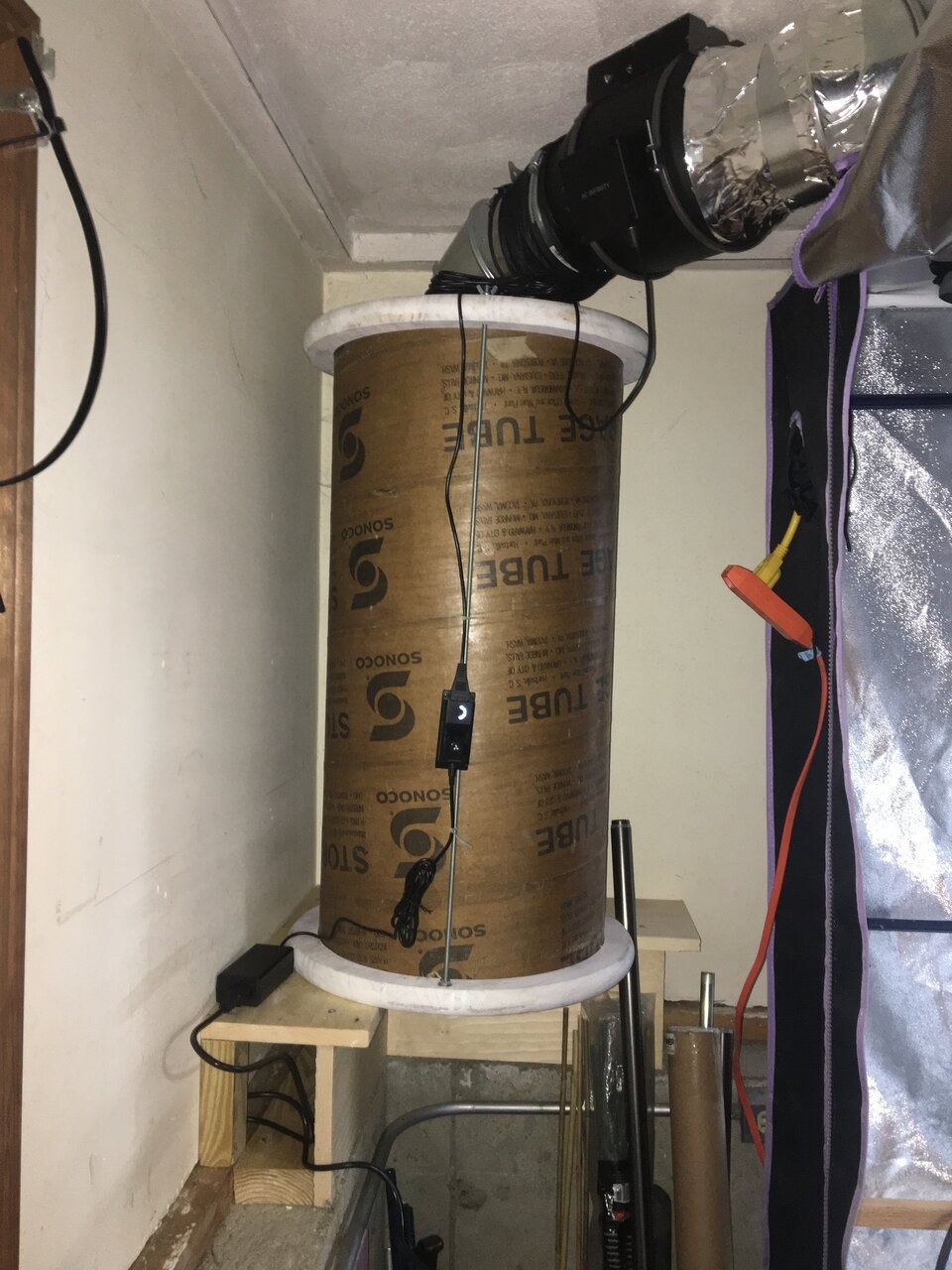
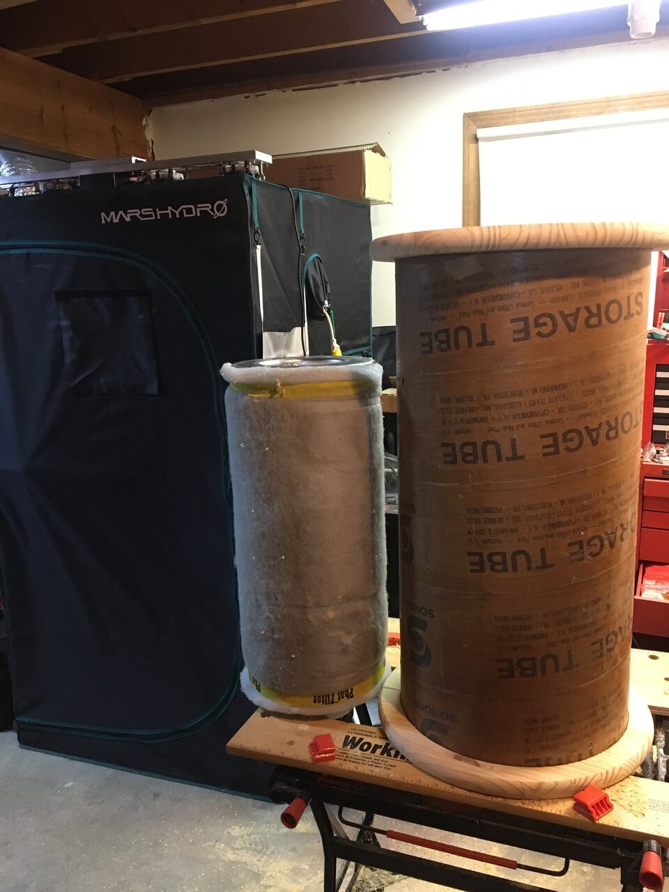
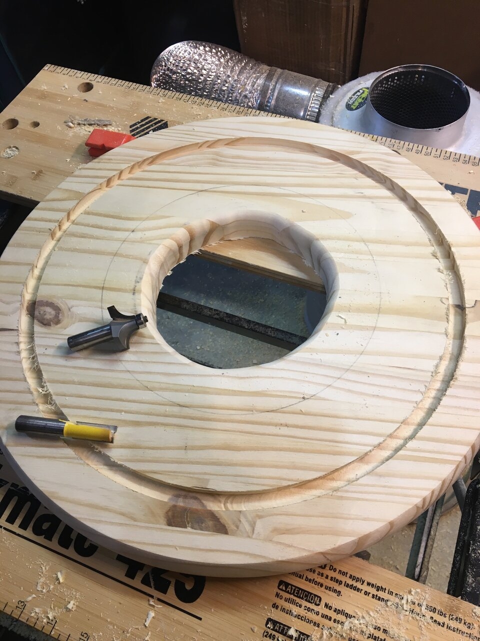
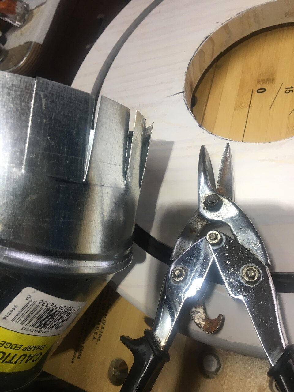
I got busy getting the 4 x 4 tent's extraction filter out of the tent. It's a 6 inch 24 inch filter. Here it is and the steps I took to make it. If you need more explanation just ask.
All set in place in the corner.
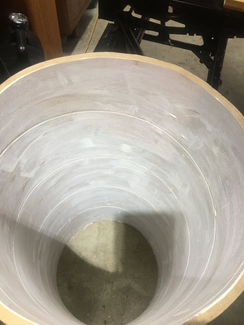
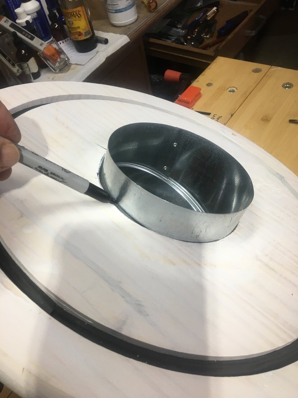
 I used a piece of 14 inch sonotube and primed the inside.
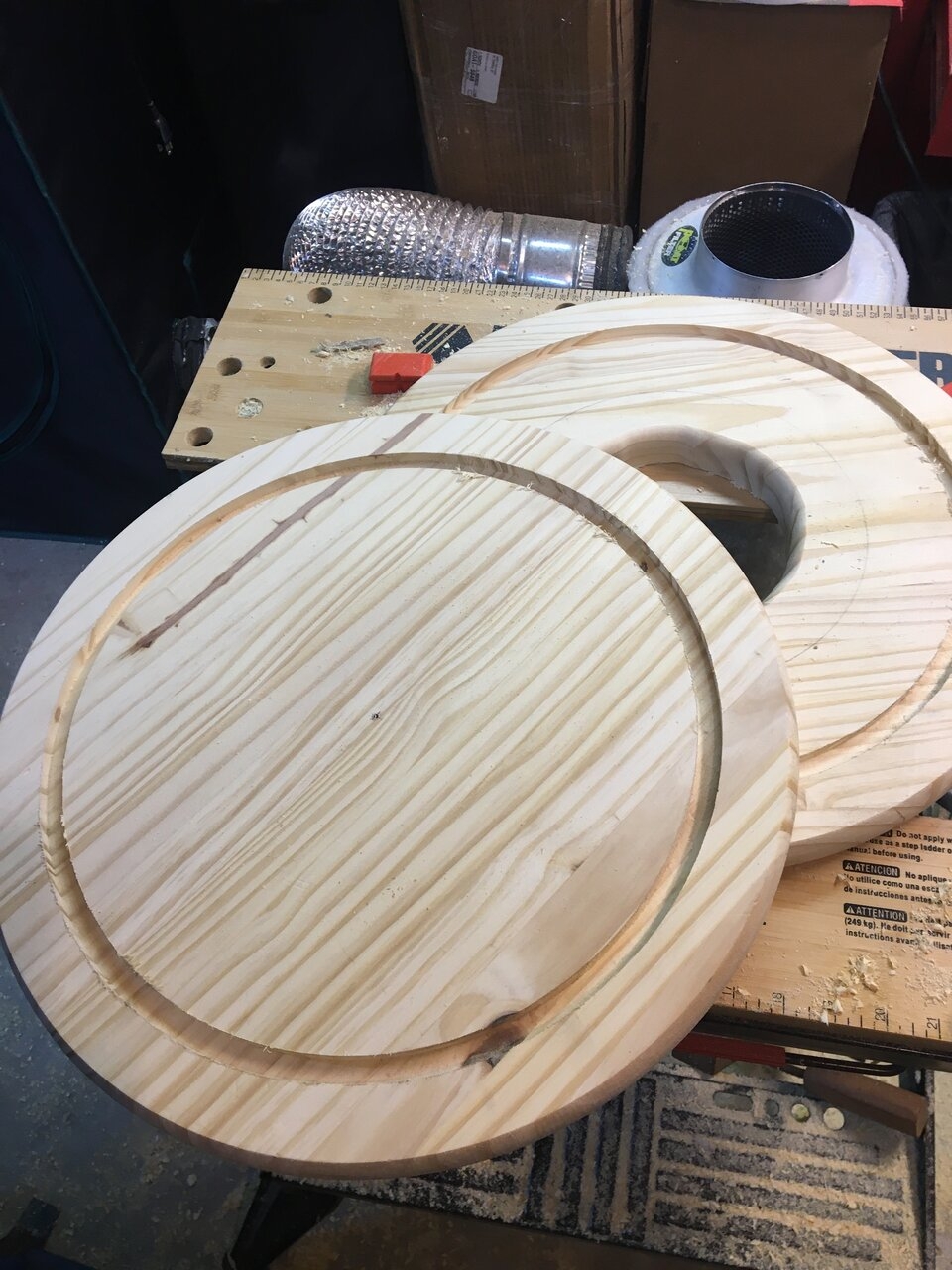
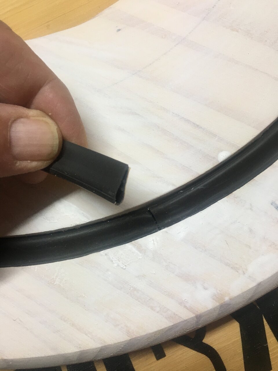
 The wood discs were pre made from the Depot. I routed a 1/2 inch rabbit around the disc to fit the gasket then the sonotube in it.
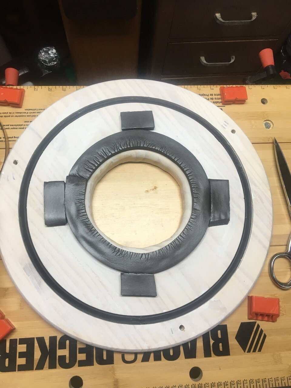 Here I make a line to depth and cut slits in the elbow.
 That's about it. The fan's bolted to the ceiling and is quiet as a mouse fart @Virgin ground
All set in place in the corner.
Similar threads
- Replies
- 1
- Views
- 5K
- Replies
- 1
- Views
- 965
- Replies
- 2
- Views
- 2K