

kelticBlue
Well-Known Member
Hi all
this is my first attempt at a DIY.
I needed to replace 4 lights on my reflector 96x5, blue ones. My tent got pretty hot last year and they may have suffered.
The manufacturer was kind enough to send me replacement ones.
Disclaimer:
This job will take a little mechanical aptitude but is not overly hard. But you need to solder the diode into the board. Practice safe working habits and take your time.
This may damage your light only attempt if you have a back up plan for lighting and are prepared to muck up your light. I am not suggesting you do this just documenting what i did. And I have not been a teacher in a very long time, any help is warmly received. I took me over 2 hours from light out of tent to back into tent.
So first a little about me. Once upon a time, about 30 years ago, I went to a technical school where they taught us to take apart and put back together lots of different things.
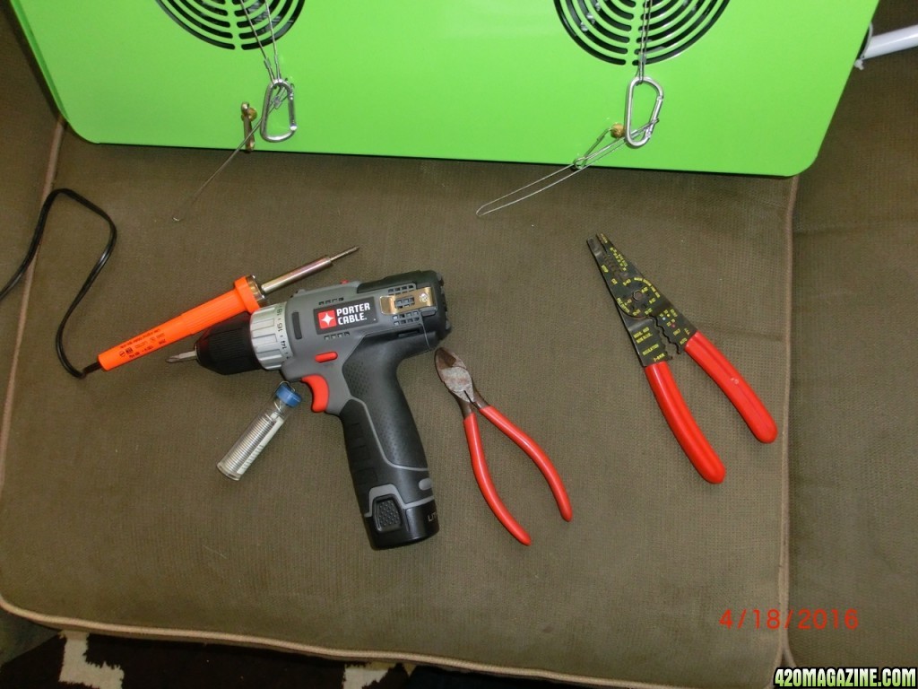
As such I once had a great set of tools not so much any more. So first i will give a look at some of the tools I used, not pictured is the arctic silver paste and a small handheld phillips-head screwdriver.
And I wish I had a better solder iron but this will do.
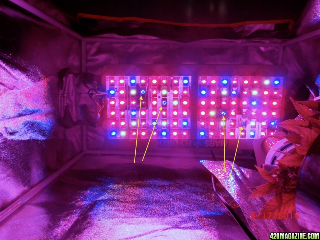
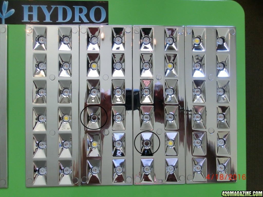
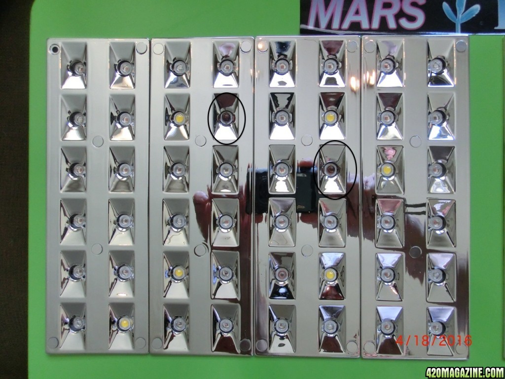
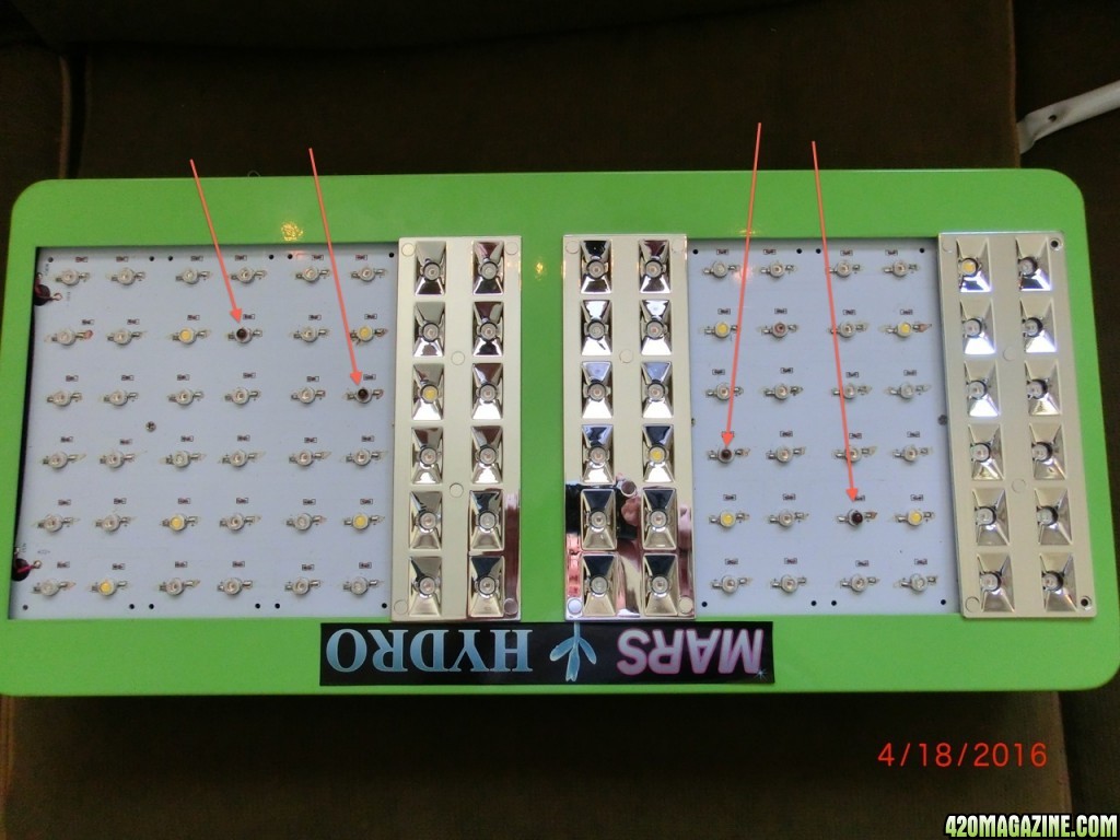
Next have a look at the light in the tent, the 4 blue diodes with the arrows. those are our subjects.
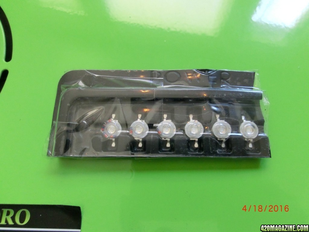
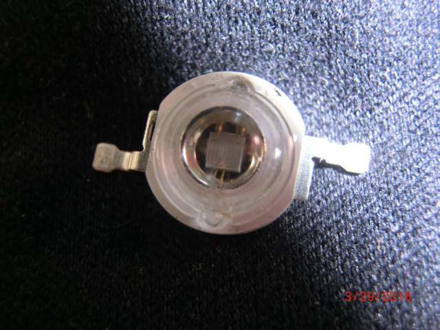
here is what the replacement diodes look like. If the positive and negative are not marked on side has a different attachment tab which I matched up with the diode I removed for proper polarity. So make a note of what the diode your remove looks like when attached.
in the package diodes and resistors
 back side of diode, positive side on right.
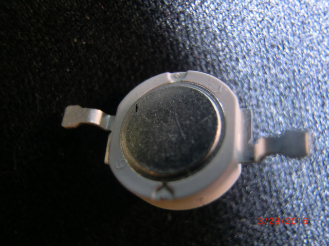
negative side on left. this will be important later
target diodes are circled
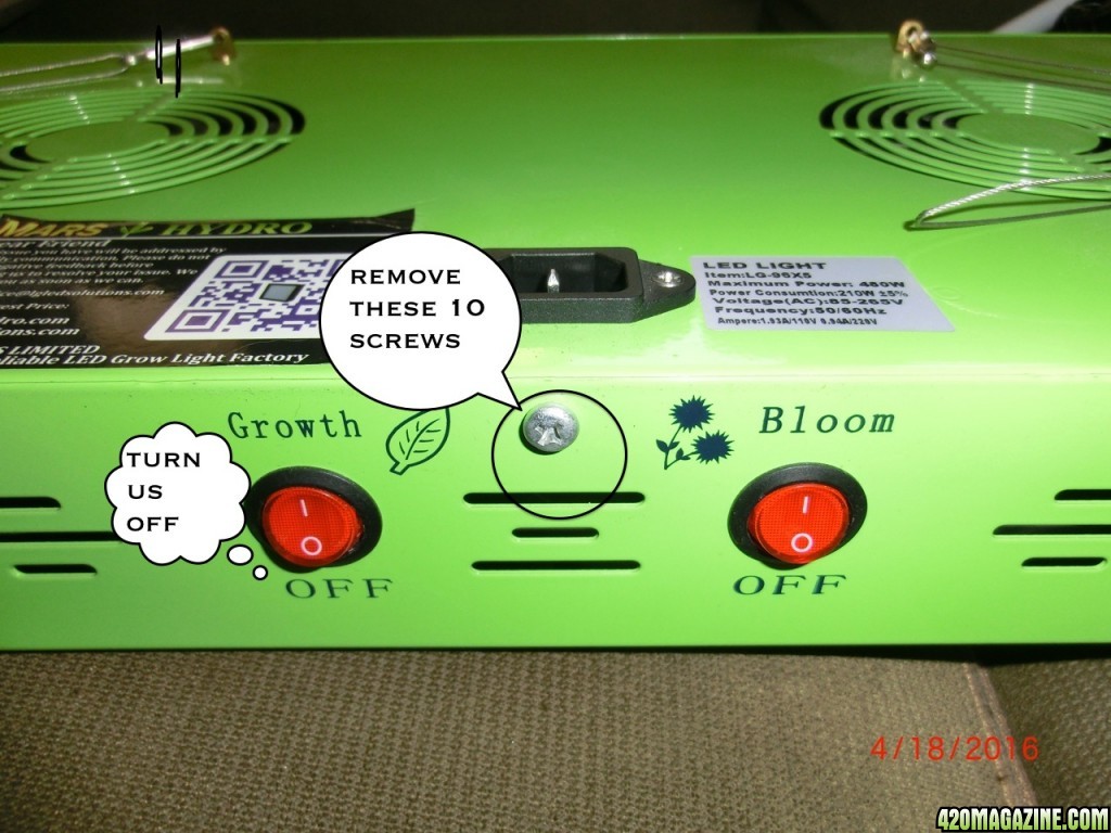
right so un-plug the electric and turn the switches off.
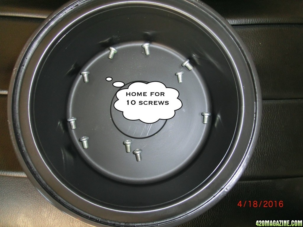
Place on a soft surface, I did reflector down, and remove 10 screws 3 on each long side and two on the shorter sides.
Have a place to keep all the screws and parts as you go.
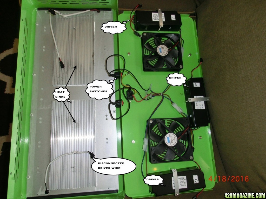
Next we want to separate the case so we can disconnect the (in my case) 3 drivers. Carfeul of the wires attached dont open with too much force.
 drivers A B C two fans I left the power switches wires connected and disconnected the drivers wires, also in the picture the heat sinks.
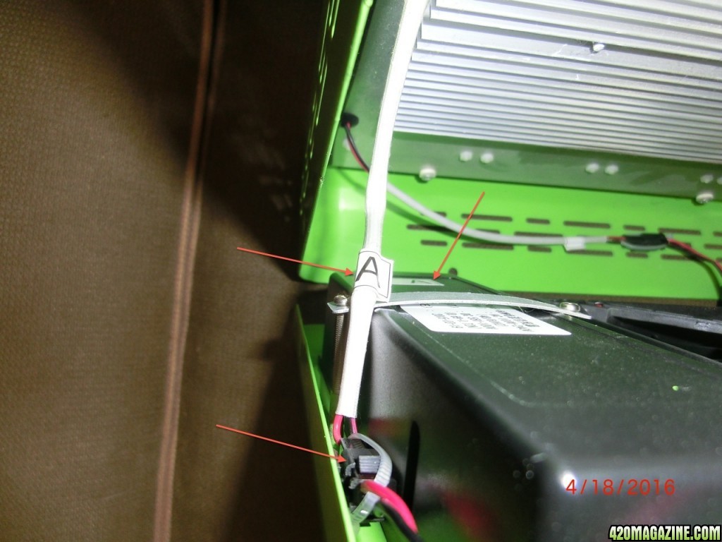
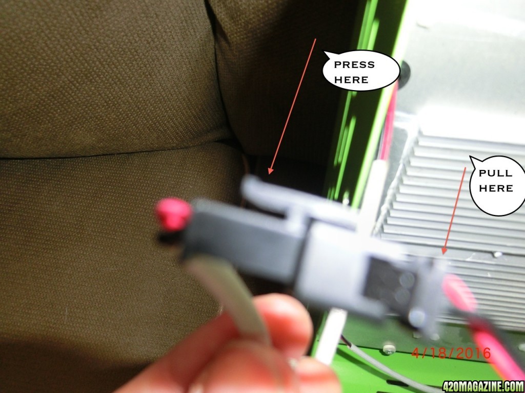
The driver wires are snug into the case next to the drivers. You need to cut the plastic tie first, then press the plastic lever to separate the connection.
note the driver and wire are labeled A, B and C for easy reconnection.
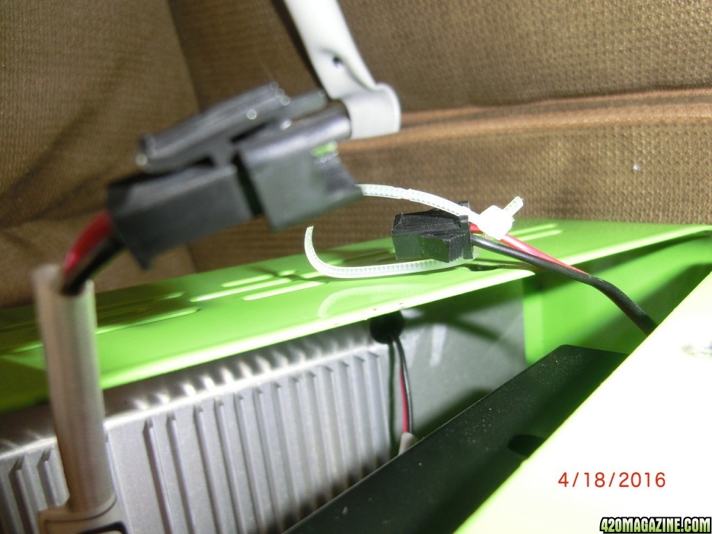
 disconnet the drivers. cut the plastic zip tie.
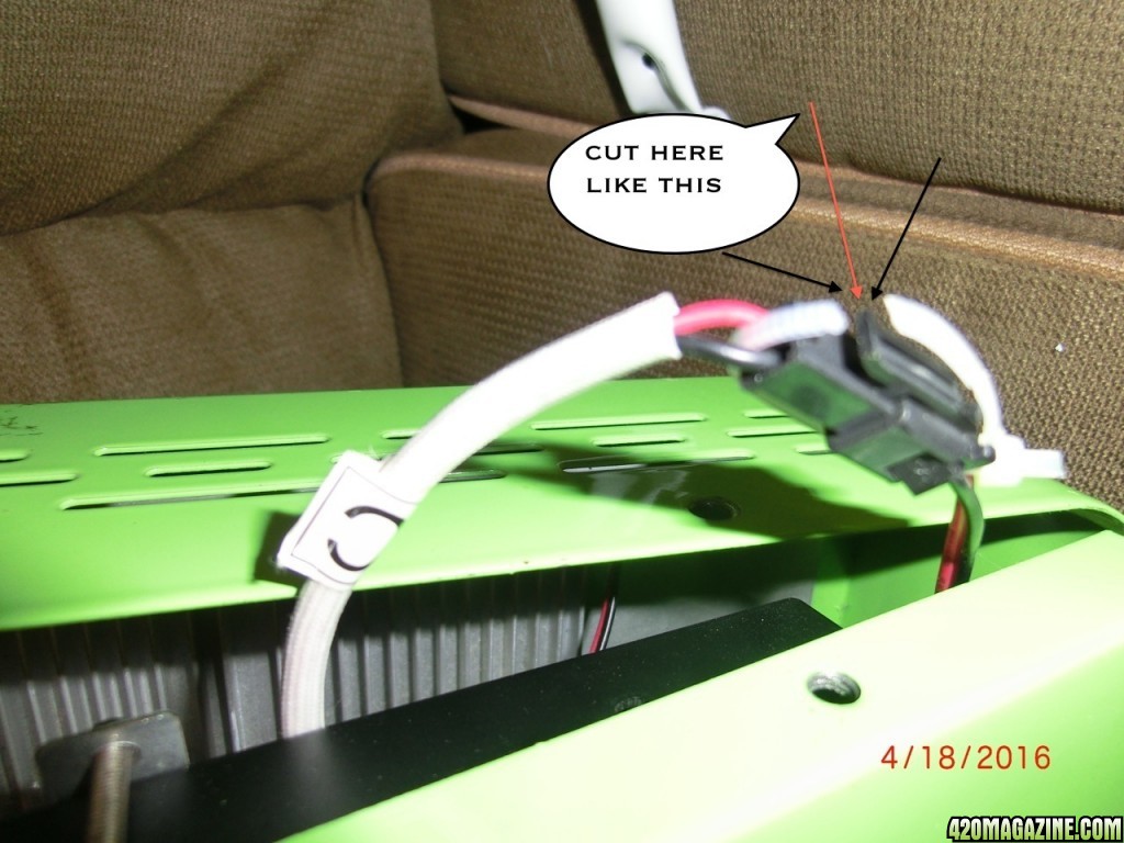 then press the latch on the plastic connector and pull
disconnected
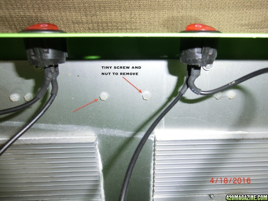
Now what I will call the first hard part. you have to remove the reflector panels on the front of the light. These are attached with little tiny plastic screws and nuts. 4 each
They run all along the sides of the heat sinks. I didn't know they were phillips head screws because the have a silver sticker cover over the head of the screws. I found out eventually.
It took some time for me to remove them mostly by hand. They are annoying and small.
Now remove the reflector panels you need not remove any where you are not replacing any diodes.
the screw head are on the reflector side.
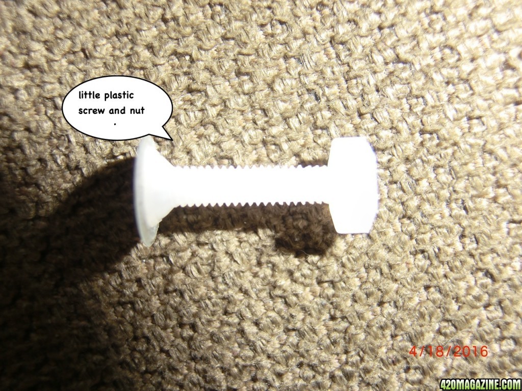
little screw and nut removed
panels removed, surface board revealed. problem diodes.
the next hard part, use the solder iron to remove the diode.
Sorry i didn't take any good pictures of the removal of the diode or replacement solder on. It is hard when you got a hot solder iron to deal with.
So advice, try to use only the solder that is already there on the board don't add more (less is more in this case). I had to add solder in two instances out of 8 solder connections. Just use very very little. Try not to over heat the board, you can see the dis-coloration where I was getting too hot for too long while removing the diodes. A good solder iron is helpful. Research 'how to solder'
When removing the diode, heat the attachment arm and use a lateral force parallel to the board to knock the light out of the solder joint leaving as much solder remain as you can.
When you replace the diode put a very small amount of thermal paste on the bottom of it, so it is flush with the board. These are surface mounted diodes they need good contact with the board for even cooling.
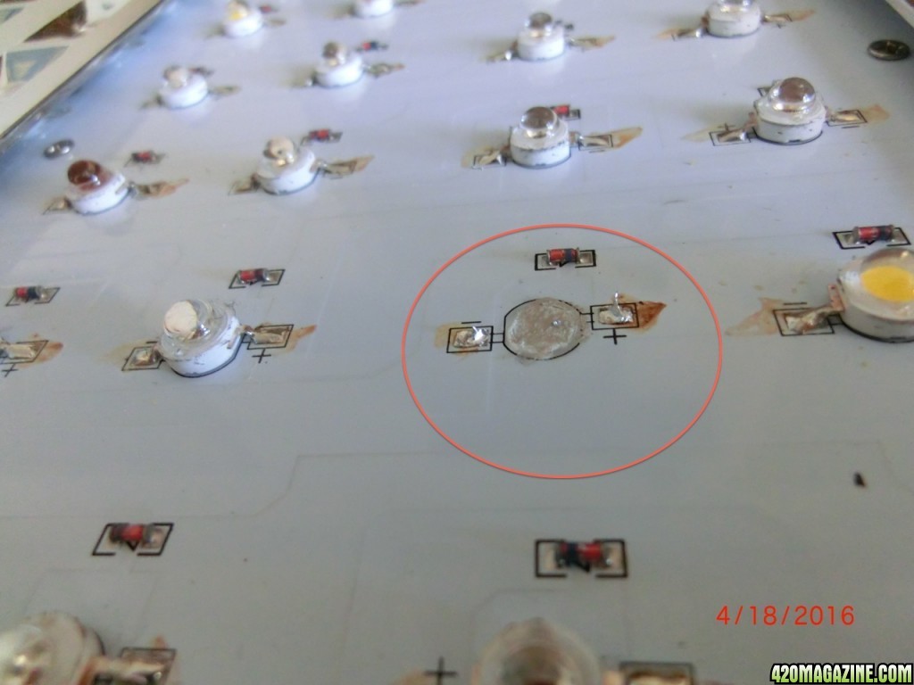
Here in the circle you can see after i removed the light. On the right, positive side a little brown discoloration from too much heat. Also note the remaining solder is enough to attach the new light. I heat the attachment arm of the light up then heat the solder then insert the arm into the solder joint of the light heating while i go. remeber the just a little thermal paste on the back of the light where it sits flush on the board, in the inner circle
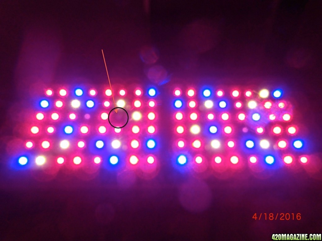
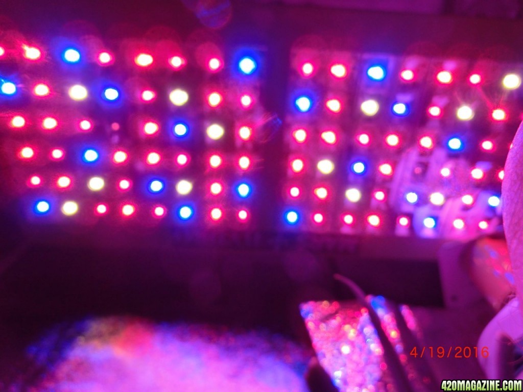
Here is the final picture you can see one diode is still not working, it needed a touch of added solder and better placement in the solder joint and now works fine. So remember to test it before you reassemble it. get the light flush with the board and dont add too much extra solder
That is about all I can remember for now, Any questions, comments or concerns?
this is my first attempt at a DIY.
I needed to replace 4 lights on my reflector 96x5, blue ones. My tent got pretty hot last year and they may have suffered.
The manufacturer was kind enough to send me replacement ones.
Disclaimer:
This job will take a little mechanical aptitude but is not overly hard. But you need to solder the diode into the board. Practice safe working habits and take your time.
This may damage your light only attempt if you have a back up plan for lighting and are prepared to muck up your light. I am not suggesting you do this just documenting what i did. And I have not been a teacher in a very long time, any help is warmly received. I took me over 2 hours from light out of tent to back into tent.
So first a little about me. Once upon a time, about 30 years ago, I went to a technical school where they taught us to take apart and put back together lots of different things.
As such I once had a great set of tools not so much any more. So first i will give a look at some of the tools I used, not pictured is the arctic silver paste and a small handheld phillips-head screwdriver.
And I wish I had a better solder iron but this will do.
Next have a look at the light in the tent, the 4 blue diodes with the arrows. those are our subjects.
here is what the replacement diodes look like. If the positive and negative are not marked on side has a different attachment tab which I matched up with the diode I removed for proper polarity. So make a note of what the diode your remove looks like when attached.
in the package diodes and resistors
negative side on left. this will be important later
target diodes are circled
right so un-plug the electric and turn the switches off.
Place on a soft surface, I did reflector down, and remove 10 screws 3 on each long side and two on the shorter sides.
Have a place to keep all the screws and parts as you go.
Next we want to separate the case so we can disconnect the (in my case) 3 drivers. Carfeul of the wires attached dont open with too much force.
The driver wires are snug into the case next to the drivers. You need to cut the plastic tie first, then press the plastic lever to separate the connection.
note the driver and wire are labeled A, B and C for easy reconnection.
disconnected
Now what I will call the first hard part. you have to remove the reflector panels on the front of the light. These are attached with little tiny plastic screws and nuts. 4 each
They run all along the sides of the heat sinks. I didn't know they were phillips head screws because the have a silver sticker cover over the head of the screws. I found out eventually.
It took some time for me to remove them mostly by hand. They are annoying and small.
Now remove the reflector panels you need not remove any where you are not replacing any diodes.
the screw head are on the reflector side.
little screw and nut removed
panels removed, surface board revealed. problem diodes.
the next hard part, use the solder iron to remove the diode.
Sorry i didn't take any good pictures of the removal of the diode or replacement solder on. It is hard when you got a hot solder iron to deal with.
So advice, try to use only the solder that is already there on the board don't add more (less is more in this case). I had to add solder in two instances out of 8 solder connections. Just use very very little. Try not to over heat the board, you can see the dis-coloration where I was getting too hot for too long while removing the diodes. A good solder iron is helpful. Research 'how to solder'
When removing the diode, heat the attachment arm and use a lateral force parallel to the board to knock the light out of the solder joint leaving as much solder remain as you can.
When you replace the diode put a very small amount of thermal paste on the bottom of it, so it is flush with the board. These are surface mounted diodes they need good contact with the board for even cooling.
Here in the circle you can see after i removed the light. On the right, positive side a little brown discoloration from too much heat. Also note the remaining solder is enough to attach the new light. I heat the attachment arm of the light up then heat the solder then insert the arm into the solder joint of the light heating while i go. remeber the just a little thermal paste on the back of the light where it sits flush on the board, in the inner circle
Here is the final picture you can see one diode is still not working, it needed a touch of added solder and better placement in the solder joint and now works fine. So remember to test it before you reassemble it. get the light flush with the board and dont add too much extra solder
That is about all I can remember for now, Any questions, comments or concerns?


") ..)
..)

 Sara you are kind.