New open source controller in the works, what features would you like most?

Which open source automation solution would you be most interested in using?

  • CO2 control

    Votes: 0 0.0%
  • Light spectrum and intensity control (requires dimmable ballast/drivers with PWM control)

    Votes: 0 0.0%

  • Total voters
    9

DrewT

Well-Known Member
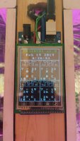
Greetings fellow DIY'ers! I've just finished building an open source multi-purpose controller. Although I learned a lot, the resulting device is more proof-of-concept then finished solution.

DSC03519-1024x670.jpg


I'm in the planning stages of the next project iteration and would appreciate your feedback. Specifically:
  1. What features do you find most useful about the controllers you use today?
  2. What features do you wish you had or would be your first choice to add?
I've also whipped up a poll to gauge feedback on a few of my ideas. I purposely crafted the selections to expose the single solution most important to you ;) . If your perfect answer isn’t listed feel free to suggest in comments. Any responses are much appreciated, thanks for your time!
 
I'm working on watering and light controls (PWM and relays) using the Arduino. Progress is slow as a few things have taken a big bite out of my time.

Watering is time of day for a set number of seconds. Electric valves and pumps will be used to direct water to each plant. A sensor detects drainage and pumps it out. (I grow in coco/perlite.) I'm currently using on pump and a Permanent Industry Programmable Timer with a single pump to water all plants simultaneously. Multiple waterings per day are easily handled with this setup.

Lights are switched by relay, and intensity is controlled with PWM.

Don't forget power fail detection and recovery ;)

I've asked, but received little interest in these projects.

Best of luck with this...
 
Greetings Old Salt! Thanks for the reply. Your application sounds interesting and it's always good to find a fellow builder.

I've asked, but received little interest in these projects.

Well darn, I'm hoping to get feedback on what applications would be most useful. I'll take what I can get ;) . Are you looking to collaborate on your projects? Everything I do is open source so it would be easy to share designs. Developing in isolation gets old pretty quick.

So did you have a top "would like to have feature", or perhaps something you're working on now?
 
Automatic watering is top priority, as that will let me leave the house for a day or three. ;)
After that, it's light control.

I have a framework for the Arduino that:
- interfaces with 2 x MCP23017s, 2 X 16 LCD(with backpack), rotary encoder & switch, and the DS1307 RTC;
- has a multi-level expandable menu system
- date / time setting of the DS1302 is complete with
- either 12 or 24 hr clock
- automatic leap year handling

Two MCP23017 I/O lines are currently used as interrupts, one for the second MCP23017, the other for the rotary switch. This leaves 30 digital I/O lines for the application. Here are the schematic and breadboard layout:

full

full

full


The LED bar and S1 are for I/O testing.
 
Very nice! We are doing very similar projects, good news for us! Your needs appear fairly straight forward unless I'm missing something. I'm using a 20x4 hd44780 LCD, a rotary encoder with R/C smoothing, and a DS3231 RTC. Forgive me for the shoddy layout, can you tell I'm not a hardware guy by trade :) ?

2019-01-12 08_03_39-Control Panel - EAGLE 8.7.1 free [OFFLINE].jpg


The latest version of my controller has both scheduled and event driven handlers. I've had stable builds running a small hydro setup for months. I change the nutrient solution every two weeks and top off every other day when I check PH (both manual but easy to automate). Is there some way that I could help with your current project? I'd be glad to point you to code I've posted. Heck, I don't have 12/24, DST, or leap implemented yet... that would be sweet!

I chose the DS1307 as it has built-in non-volatile memory, and is capable of generating a timed interrupt via SQW. What I don't like about it is the usage of BCD values. I wrote BCD <--> decimal conversion routines to take care of that. SQW is set to a 1Hz square wave, and the ISR divides this by 60, and raises a flag once per minute to update LCD time and fire off any time of day events. I plan on storing current system status on the DS1307, including last processed time for power fail detection / recovery.

I've written my own I2C/RTC library. This circumvents some of the problems with the shipped I2C library where you can't read/write more than a few bytes. There are 22 configuration registers on the MCP23017, and initially I was left scratching my head when my sketch failed.

The switch on the rotary encoder generates an interrupt, and is an input for the Arduino. The interrupt is turned off while the menu subsystem is active. Exiting the menu restores the interrupt. De bouncing is done with delays in the sketch.

I joined Udemy. My core code is posted there in the Tech Explorations™ Arduino Step by Step Getting Serious course at: https://www.udemy.com/arduino-sbs-getting-serious/learn/v4/questions/5505308. The I2C/RTC library is on github: Old-Salt/Arduino-libraries. The courses Tech Explorations™ Basic electronics for Arduino Makers, Tech Explorations™ Arduino Step by Step: Getting Started, and Tech Explorations™ Arduino Step by Step Getting Serious are well worth the cost, even for those with an electronic or programming background. They've saved me countless hours whe interfacing various devices with the Arduino.
 
Thanks for the detailed explanation! You bring up a few questions for me considering my design. These questions concern my understanding of design so please don't take them as criticism :) .


ISR divides this by 60, and raises a flag once per minute to update LCD


So the RTC flags the control loop via an ISR correct? Is this indicative of how the display refresh works in general for your design? If not, then you have at least two distinctly separate methods for signaling display updates. Also, this design requires your time source to have and maintain interrupt capacity... which limits the variety of time sources you can use correct? I implement a bridged abstraction for all external components which allows emulation in a multi-build architecture. In my case, each abstraction would need to maintain its own ISRs to update system time correct?


storing current system status on the DS1307


If the MCU has EEPROM, why not store state there? In my case I keep all non-volatile state stored on the MCU as it's a great way to centralize state structures including commit, retrieval, and serialization. Would distributing state to external components increase complexity of the design?


Exiting the menu restores the interrupt


This leads me to believe time stands still on your device while the encoder/menu is active? Unless you menu navigation sub routines maintain system time polling (would conflict with ISR push model) then you effectively prohibit any async events that depend on correct system time (such as scheduled tasks). I don't want to miss a scheduled watering because I'm poking through the menu modifying some configs.


It's great to meet someone working on the same problems! Thanks so much for dropping into the thread! I'll ask again, how might I be able to assist you in a way that benefits our collaboration? I'm currently working to implement a HM-10 BLE (Bluetooth) component to allow configuration of wireless peripheral modules without a user interface. Do you have any experience with that by chance?
 
C++:
/* Title: Automatic watering System 1.0
*
* By: *** Old Salt *** Oct 2018
*
* Description:
*   - work in progress
*
* Requirements:
*   - I2C LCD 16 x 2
*   - rotary encoder with switch (see below for connections)
*   - MCP23017 (Ports A & B all bits as outputs)
*   - DS1307 RTC
*
* Comments:
*   - MCP23017 outputs are connected through LEDs and current limiting
*     resistors for development & testing
*/
  #include <rtc.h>
  #include <LiquidCrystal_I2C.h>
  const byte MCP0_addr = 0x20;            // MCP23017 #0 I2C address
  const byte MCP1_addr = 0x21;            // MCP23017 #1 I2C address
  const byte LCD_addr = 0x27;             // LCD I2C address

  rtc RTC = rtc();                        // create RTC object
  LiquidCrystal_I2C lcd(LCD_addr,16,2);   // Initialize LCD 16 cols x 2 rows


// define pins and global variables used for interrupts
  const byte clockInterruptPin = 2;       // 1 second timer (SQW from DS1307)
  const byte MCPinterruptPin = 3;         // INT A from MCP0
  bool clockInterruptFlag = false;        // flag set by ISR_RTC
  bool MCPinterruptFlag = false;          // flag set by ISR_MCP
  byte expandedInterrupts[] = {0, 0, 0, 0}; // 0 = MCP0 Port A (Bit 0 = Rotary SW, Bit 1 = MCP1 INT A)
                                          // 1 = MCP0 Port B, 2 = MCP1 Port A, 3 = MCP1 Port B
                                          // system must be configured before pin usage is known.

// MCP23017 registers: initialization values, will change within the sketch
//                    IODIR        IOPOL      GPINTEN     DEFVAL      INTCON       IOCON
  byte MCP0reg[] = {0x03, 0x00, 0x00, 0x00, 0x03, 0x00, 0x03, 0x00, 0x03, 0x00, 0x40, 0x40,
                    0x00, 0x00, 0x00, 0x00, 0x00, 0x00, 0x00, 0x00, 0x00, 0x00};
//                    GPPUA        INTF       INTCAP       GPIO        OLAT
  byte MCP1reg[] = {0x01, 0x00, 0x00, 0x00, 0x01, 0x00, 0x01, 0x00, 0x01, 0x00, 0x40, 0x40,
                    0x00, 0x00, 0x00, 0x00, 0x00, 0x00, 0x00, 0x00, 0x00, 0x00};

// Rotray Encoder & Switch connections, encoder center & remainitg switch arm are grounded
  const byte rotary_A = 4; // encoder wiper A, use 10K pull-up resistor
  const byte rotary_B = 5; // encoder wiper B, use 10K pull-up resistor
  const byte rotary_S = 6; // Switch leg, use 10K pull-up resistor, used as input
                           //   also connected to MCP0 Port A bit 0 for an interrupt                     

  bool menuActive = false;                // set/reset by menu system
  bool barDir=false;                      // dir = right to left  *** Test & debug ***

// Initialize the menu array (limit to 128 item, 0-127 including exit)
  struct menu_record{                     // custom data structure for menu items
    byte prev;                            // index of menu_item to the left
    byte next;                            // index of menu_item to the right
    byte task;                            // bit 7 set means jump to menu_item specified by bits 0-6
    char label[17];                       // display name of this menu_item
  };
  const byte menu_length = 9;             // number of menu items
  menu_record menu_item[menu_length];


void setup(){
// assign encoder & switch inputs
  pinMode(rotary_A, INPUT);
  pinMode(rotary_B, INPUT);
  pinMode(rotary_S, INPUT);

// Initialize RTC
  RTC.noSeconds = true;
  RTC.getTimeStr();
  attachInterrupt(digitalPinToInterrupt(clockInterruptPin), ISR_RTC, FALLING);
  RTC.setSQW(0x10);                            // enable SQW at 1Hz

// initialize MCP23017s (assumes IOCON.BANK=0 from power on reset)
  RTC.I2C.setDeviceAddress(MCP0_addr);          // Select MCP0
  RTC.I2C.seqWrite(0x00, MCP0reg, 0x00, 0x0D);  // write configuration registers
  RTC.I2C.seqRead(0x0E, MCP0reg, 0x0E, 0x15);   // read registers to clear any interrupts
  RTC.I2C.setDeviceAddress(MCP1_addr);          // Select MCP1
  RTC.I2C.seqWrite(0x00, MCP1reg, 0x00, 0x0D);  // write configuration registers
  RTC.I2C.seqRead(0x0E, MCP1reg, 0x0E, 0x15);   // read registers to clear any interrupts
  attachInterrupt(digitalPinToInterrupt(MCPinterruptPin), ISR_MCP, FALLING);
  pinMode(rotary_S, INPUT);         // also generates interrupt at MCP0 bit 0

// initialize LCD
  lcd.init();
  lcd.backlight();
  disp_default();                   // show the default LCD content

// Populate the menu...
  menu_populate();
}  // end of setup() ***********************************************************************

void menu(){
// menu navigation system
  byte menu_index = 1;                                    // Current menu_item, Start at top level/Setup
  int EncSwitch = 0;
  disp_menu();                                            // display screen for menu system
  menuActive = true;
  do{
    lcd.setCursor(0, 1);                                  // update display with current menu_item[].label
    lcd.print(menu_item[menu_index].label);
    EncSwitch = getEncSwitch();
    switch(EncSwitch){
      case 1:                                             // CW rotation - goto next menu_item[]
        menu_index = menu_item[menu_index].next;
        break;
      case 2:                                             // CCW rotation - goto previous menu_item[]
        menu_index = menu_item[menu_index].prev;
        break;
      case 3:                                             // Switch pressed - action needed
        if(menu_item[menu_index].task & 0x80){            // change menu level?
          menu_index = menu_item[menu_index].task & 0x7F; // strip bit 7 from task
        }
        else {
          do_it(menu_item[menu_index].task);
        }
        break;
      default:
        break;
    }  // end switch(EncSwitch)
  } while(menuActive);                                    // menuActive set false in do_it
}  //  End of menu()

void menu_populate(){
// populate the menu system: Main Menu
  menu_item[0] = (menu_record) {3,1,0,"   Exit Menu    "};
  menu_item[1] = (menu_record) {0,2,127,"  Schedule      "};
  menu_item[2] = (menu_record) {1,3,127,"  Reports       "};
  menu_item[3] = (menu_record) {2,0,128+4,"  Setup         "};        // jump to Set Date

  // populate the menu system: Setup sub-menu
  menu_item[4] = (menu_record) {8,5,10,"  Set Date      "};
  menu_item[5] = (menu_record) {4,6,11,"  Set Time      "};
  menu_item[6] = (menu_record) {5,7,127,"  Configure     "};
  menu_item[7] = (menu_record) {6,8,127,"  Calibrate     "};
  menu_item[8] = (menu_record) {7,0,128+3," Back: Main Menu"};    // Return to Main Menu : Setup
}  // end of menu_populate()


void loop() {
  byte interruptTask;               // used to determine what interrupt task to execute
// check for meaningfull work
  if(clockInterruptFlag){
    RTC.getTimeStr();
    lcd.setCursor(8, 0);
    lcd.print(RTC.timeStr);
    clockInterruptFlag = false;
  }

  if(MCPinterruptFlag){             // check for new MCP interrupt
    updateMCPinterrupts();
  }

// scan the interrupt flags to determine if one needs to be processed
// priority is expandedInterrupts[0] bit 0 for highest expandedInterrupts[3] bit 7 for lowest
  interruptTask = 0;
  do {                         
    if(bitRead(expandedInterrupts[interruptTask/8], (interruptTask%8))){
      break;                        // break exits the do...while loop
    }                               //
    interruptTask++;                // exit value indicates the first flag found
  } while(interruptTask < 32);      // exit value of 32 means no flags at this time

  if(interruptTask != 32){          // only execute switch statement if a flag was raised
// direct code execution as appropriate to interruptTask
    switch (interruptTask) {
      case 0: {                     // interrupt caused by rotary switch on MCP0 bit 0
        menu();                     // menu functions
        expandedInterrupts[0] = expandedInterrupts[0] & 0xFE; // clear interrupt request flag.
        break;
      }
      case 66: {                    // interrupt caused by switch on MCP1 bit 0
        RTC.I2C.setDeviceAddress(MCP1_addr); // select MCP1
        do {                                 // do...while switch is pressed
          MCP1reg[0x12] = RTC.I2C.read(0x12);
        } while (!(MCP1reg[0x12] & 0x01));
        expandedInterrupts[2] = expandedInterrupts[2] & 0x00; // clear interrupt request flag.
        break;
      }
      default: {                    // code to execute when no case matches
        break;
      }
    } // switch
// code to re-enable MCP interrupt
    if(interruptTask < 16){         // it's on MCP0
      if (interruptTask < 8){       // it's on Port A
        bitSet( MCP0reg[0x04], interruptTask%8); // set the bit in GPINTENA
      } else {
        bitSet( MCP0reg[0x05], interruptTask%8); // set the bit in GPINTENB
      }
      RTC.I2C.setDeviceAddress(MCP0_addr);          // select MCP0
      RTC.I2C.seqWrite(0x04, MCP0reg, 0x04, 0x05);  // write to the registers
    } else {                        // it's on MCP1
      if (interruptTask < 24){      // it's on Port A
        bitSet( MCP1reg[0x04], interruptTask%8); // set the bit in GPINTENA
      } else {
        bitSet( MCP1reg[0x05], interruptTask%8); // set the bit in GPINTENB
      }
      RTC.I2C.setDeviceAddress(MCP1_addr);          // select MCP0
      RTC.I2C.seqWrite(0x04, MCP1reg, 0x04, 0x05);  // write to the registers
    } // end code to re-enable MCP interrupt
  }   // if (interruptTask != 32)


// *** Test & debug ***
// interruptable 'make work' routine (LED bars)
static byte barLed=1;
bool barOvfl = false;               // overflow during shift operations

// Send current MCP23017 data:      //Port A is left side of bar LEDs
  RTC.I2C.setDeviceAddress(MCP1_addr);
  RTC.I2C.write(0x13, barLed);      // Write a single byte

  if(barDir){                       // LED moves left to right
    if(barLed & 0x01){              // check for bit 0 in LSB
      barOvfl = true;
    }
    barLed = (barLed >> 1);         // shift low order byte right one bit
    if (barOvfl){                   // check for bit 0
      barLed = barLed | 0x80;       // send it to bit 7
      barOvfl = false;              // reset the flag
    }
  }
  else {                            // LED moves right to left
    if(barLed & 0x80){              // check bit 7 of the MSB
      barOvfl = true;
    }
    barLed = barLed << 1;           // shift MSB left one bit
    if (barOvfl){                   // check for bit 0
      barLed = barLed | 0x01;       // send it to bit 7
      barOvfl = false;              // reset the flag
    }
  }
  delay(80);
}  // end of loop()  ***********************************************************************

void disp_default(){
// default LCD content
  lcd.clear();
  lcd.print("AWS 1.0 ");
  RTC.getTimeStr();
  lcd.print(RTC.timeStr);
  lcd.setCursor(0, 1);
  lcd.print("   Active ...   ");
}

void disp_menu(){
// menu system LCD content
  lcd.clear();
  lcd.print("AWS 1.0     Menu");
}

unsigned char getEncSwitch() {
// Read encoder and switch input pins and process events.
// Based on Rotary, Copyright 2011 Ben Buxton.
// returns 1 for CW rotation, 2 for CCW rotation, and 3 for awitch press

  const unsigned char ttable[6][4] = {              // Half-step state table
    {0x3 , 0x2, 0x1,  0x0}, {0x23, 0x0, 0x1,  0x0}, //(emits a code at 00 and 11)
    {0x13, 0x2, 0x0,  0x0}, {0x3 , 0x5, 0x4,  0x0},
    {0x3 , 0x3, 0x4, 0x10}, {0x3 , 0x5, 0x3, 0x20}
  };
  unsigned char pinstate = 0;
  unsigned char state = 0;
  unsigned char rstate = 0;
  do{
    pinstate = (digitalRead(rotary_B) << 1) | digitalRead(rotary_A);
    state = ttable[state & 0xf][pinstate];
    rstate = state & 0x30;
    while (digitalRead(rotary_S) == 0) {        // Check for pressed switch
      rstate = 48;                              // then wait until it is released
    }
  } while (rstate == 0);
  delay(40);                                    // debounce delay
  return (rstate / 16);                         // 1 = CW, 2=CCW; 3=Switch pressed
}

int getNumber(int number, int minNumb, int maxNumb, int dispX, int dispY){
// get a number using the rotary control, displayed at dispX, dispY on the LCD
// the number is constrained by minNumb and maxNumb, and wraps around from max <-> min
  int EncSwitch = 0;
  do{                                      // dispx, y are for least significant bit
    lcd.setCursor(dispX+1, dispY);         // (limits 00 - 00) leading zeros are displayed
    lcd.blink();
    EncSwitch = getEncSwitch();
    switch(EncSwitch){
      case 1:                               // CW rotation - increase number
        number++;
        if(number > maxNumb){               // number wraps around from max -> min
          number = minNumb;
        }
        break;
      case 2:                               // CCW rotation - decrease number
        number--;
        if(number < minNumb){               // number wraps around from min -> max
          number = maxNumb;
        }
        break;
      default:
        break;
    }  // end switch(EncSwitch)
    lcd.setCursor(dispX, dispY);
    if (number<10) lcd.print("0");
    lcd.print(number);
  } while(EncSwitch != 3);                  // Rotary switch accepts current value
  lcd.noBlink();
  return number;
}

void do_SetDate(){
  lcd.clear();
  lcd.print("AWS 1.0 Set Date");
  lcd.setCursor(3, 1);
  RTC.getTimeStr();
  lcd.print(RTC.dateStr);
  RTC.RTCdec[6] = getNumber(RTC.RTCdec[6], 0, 99, 5, 1);
  RTC.RTCdec[5] = getNumber(RTC.RTCdec[5], 1, 12, 8, 1);
  RTC.RTCdec[4] = getNumber(RTC.RTCdec[4], 1, RTC.daysInMonth(RTC.RTCdec[5], RTC.RTCdec[6]), 11, 1);
  RTC.setTime();
  delay(1000);
}

void do_SetTime(){
  bool format12 = !RTC.clock12;
  lcd.clear();
  lcd.print("AWS 1.0 Set Time");
  lcd.setCursor(0, 1);
  lcd.print(" Format: 12 hr");
  do {
    format12 = !format12;
    lcd.setCursor(9, 1);
    if (format12) lcd.print("12");
      else lcd.print("24");
  } while(getEncSwitch() != 3);
  lcd.setCursor(0, 1);
  lcd.print("                ");
  lcd.setCursor(4, 1);
  RTC.clock12 = format12;
  RTC.noSeconds=false;
  RTC.getTimeStr();
  lcd.print(RTC.timeStr);
  if(format12) RTC.RTCdec[2] = getNumber(RTC.RTCdec[2], 0, 11, 4, 1);
    else RTC.RTCdec[2] = getNumber(RTC.RTCdec[2], 0, 23, 4, 1);
  RTC.RTCdec[1] = getNumber(RTC.RTCdec[1], 0, 59, 7, 1);
  RTC.RTCdec[0] = getNumber(RTC.RTCdec[0], 0, 59, 10, 1);
  if (RTC.clock12) {
    RTC.am = !RTC.am;
    lcd.blink();
    lcd.setCursor(13, 1);
    do {
      RTC.am = !RTC.am;
      if (RTC.am) lcd.print("AM");
        else lcd.print("PM");
        lcd.setCursor(13, 1);
      } while(getEncSwitch() != 3);
    lcd.noBlink();
    }
  RTC.setTime();
  RTC.noSeconds=true;
  delay(1000);
}

void do_it(int action){
// carry out action specified by the menu
    switch(action){
      case 0:                       // Exit menu system
        disp_default();             // restore default display
        barDir = !barDir;           // *** Test & debug ***
        menuActive = false;         // exit the menu system
        break;

      case 10:                      // Set Date (actions 1-9 left free for future use)
        do_SetDate();
        disp_default();             // restore default display
        break;

      case 11:                      // Set Time
        do_SetTime();
        disp_default();             // restore default display
        break;

      default:                      // function not implemented
        lcd.setCursor(0, 1);
        lcd.print("Not Implemented!");
        delay(1000);                // show it for one second
        break;
    }  // end of switch(action)
}  // end of do_it()

void updateMCPinterrupts(){
// interrupt flags are read and OR'd with current expandedInterrupts for service
// this ensures the interrupt is not lost if another is raised.  The appropriate
//  flag is reset at the end of loop().
  RTC.I2C.setDeviceAddress(MCP0_addr);
  RTC.I2C.seqRead(0x0E, MCP0reg, 0x0E, 0x0F);
  expandedInterrupts[0] = expandedInterrupts[0] |  MCP0reg[0x0E];
  expandedInterrupts[1] = expandedInterrupts[1] |  MCP0reg[0x0F];
  if(MCP0reg[0x0E] & 0x02){           // check for cascaded interrupt from MCP1
    RTC.I2C.setDeviceAddress(MCP1_addr);
    RTC.I2C.seqRead(0x0E, MCP1reg, 0x0E, 0x11);
    expandedInterrupts[2] = expandedInterrupts[2] |  MCP1reg[0x0E];
    expandedInterrupts[3] = expandedInterrupts[3] |  MCP1reg[0x0F];
    expandedInterrupts[0] = expandedInterrupts[0] & 0xFD;   // clear cascading interrupt bit
// disable current interrupt flag on MCP1
    MCP1reg[0x04] = MCP1reg[0x04] ^ MCP1reg[0x0E]; // XOR GPINTEN with INTF
    MCP1reg[0x05] = MCP1reg[0x05] ^ MCP1reg[0x0F];
    RTC.I2C.setDeviceAddress(MCP1_addr);
    RTC.I2C.seqWrite(0x04, MCP1reg, 0x04, 0x05);
  }
  else {
// disable current interrupt flag on MCP0
    MCP0reg[0x04] = MCP0reg[0x04] ^ MCP0reg[0x0E]; // XOR GPINTEN with INTF
    MCP0reg[0x05] = MCP0reg[0x05] ^ MCP0reg[0x0F];
    RTC.I2C.setDeviceAddress(MCP0_addr);
    RTC.I2C.seqWrite(0x04, MCP0reg, 0x04, 0x05);
  }
// clear MCP0 interrupt
  RTC.I2C.setDeviceAddress(MCP0_addr);
  RTC.I2C.seqRead(0x10, MCP0reg, 0x10, 0x11);
  MCPinterruptFlag = false;         // reset interrupt service request
}

void ISR_MCP (){                // combined interrupts from MCP0 & MCP1
  MCPinterruptFlag = true;      // set interrupt service request
}
void ISR_RTC (){              // raises flag once per minute
  static byte secCount;       // seconds counter
  secCount++;
  if(secCount == 60){
    secCount = 0;
    clockInterruptFlag = true;
  }
}

So the RTC flags the control loop via an ISR correct?
Yes
If the MCU has EEPROM, why not store state there?
EEPROM has a limited number of writes that it can accomodate.
This leads me to believe time stands still on your device while the encoder/menu is active?
No, the timer is on a separate interrupt.
Do you have any experience with that by chance?
No, my preference would be WiFi rather than Bluetooth. Any device with a browser would then be able to access the microcontroller. There would be no need to develop separate IOS, Android, and computer apps - one size fits all. Security would be implemented by a combination of restricting the IPs allowed access, passwords, and encryption.
 
Mind if I follow along...working on a simple Arduino project myself for Lights, Pumps, Temp and Humidity...maybe more later...lol
I have written some basic code to do the timers for lights and pumps with RTC and relay boards...and have the temp sensors finally wired in and working...so far.
Next I have to do Humidity and SD read/writes...I have a 2.8" touch LCD w/touch screen...so that I will use for menus when I get to that point some day. :p
 

Attachments

  • 20190219_183029.jpg
    20190219_183029.jpg
    388 KB · Views: 160
I have written some basic code

Very cool @GR33NT0Y! Please do let me know if want to sync on code bits. I've published a recent project that has many of the same features that you're building.

I have a 2.8" touch LCD w/touch screen

Oh yeah, that looks cool as heck! I've been debating the local display (lcd/tft) but just haven't been able to justify the expense and added complexity. I figure most of us have great input interfaces already, in the form of cellular phones we use every day. After pricing out the cost of adding displays to a component module I keep coming back to using my phone as the interface and serving module management features over HTTP and MQTT. What do you like most about your display? Would you prefer using it over using a phone display to manage the device?

Thanks for sharing!
 
I programmed my arduino to use a 4 line lcd display. It will print out all the current configuration values pulled from the server during start up then display all the sensor values. I found this useful when plugging it in to make sure everything is working since my computer and grow space are in separate areas. So for me, displays are useful for debugging, but I don't use it after everything is working. For getting information, nothing beats a large web page with tons of history on it, and that just won't fit on a small display.
 
I programmed my arduino to use a 4 line lcd display. It will print out all the current configuration values pulled from the server during start up then display all the sensor values. I found this useful when plugging it in to make sure everything is working since my computer and grow space are in separate areas. So for me, displays are useful for debugging, but I don't use it after everything is working. For getting information, nothing beats a large web page with tons of history on it, and that just won't fit on a small display.
True enough, but the integrated display also provides an on-site indication that everything is working. The remote is great for history, and programming the unit with operational parameters.
 
True enough, but the integrated display also provides an on-site indication that everything is working. The remote is great for history, and programming the unit with operational parameters.

I have 2x16 on my modules as well, and just seeing the current time correctly is a good indication that things are running properly...
 
just seeing the current time correctly is a good indication that things are running properly

Agreed. In my prototyping I've found that although a display is good at indicating operational status, a buzzer and multi-color LED is a better fit in most applications. The sound/color combinations make it extremely easy to identify potential issues quickly. The reduction in device size/complexity, the cost savings on parts/enclosure, and the ability to go water-resistant (IP 64+) seem like a fair trade to me. One major knock is the remote single point of failure. Zero config or detailed debugging without a powered device with operational WiFi.
 
I also have an RGB LED, it stays green while status is ok, turns red if a problem, and flashes blue while sending data to the server...
 
It's not overly difficult to make a device water-resistant. The enclosures are already pierced for cabling. Affixing a piece of plexiglass and using capacitive touch buttons is a minor job. The cost is minor as well. The LCD and buttons can be had for under $7.50. In my opinion having a display on a device is very much worth it.
 
Good points guys, really appreciate your views on the matter!

I also have an RGB LED

Do you feel the status LED is redundant as the display could also serve as a status indicator? I had both as well but found the display was almost never used because the LED diag behaviour was good enough 95% of the time.

Affixing a piece of plexiglass and using capacitive touch buttons is a minor job

That made me think, can you use a touch screen behind a piece of plexiglass and still have it respond acceptably to input?

The LCD and buttons can be had for under $7.50

That would easily be 50% or more of the total BOM cost for most of my component module designs. I guess I could design a handheld display that would directly interface with a module over the rs485 connection. This could be reused on any module, thus removing the requirement that a scaled system needs a display on every component module. It would require supporting two distinct user experiences (orchestrated vs direct connect) but it may prove a popular feature.
 
Back
Top Bottom