Steve McStoferson
New Member
real cool stuff going on in here, im a programmer and want to do something similar like this to completely automate a hydro feeding system.
How To Use Progressive Web App aka PWA On 420 Magazine Forum
Note: This feature may not be available in some browsers.
You can add ethernet, WiFi, it connects via USB for live interface. So all the things you mention are possible.
 )
)
Hello
Stumbled upon your thread
I have always dreamed about a arduino grow controller but i am a hardware guy and have problem with the software part, hehe Have played with servos and night riding light at most,
So i will gladly follow this tutorial and program the shit out of the arduino, hehe
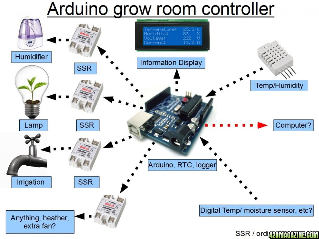
Have you ever thought about Solid State Relays? they are 1usd each at ebay.
heheIsn't there an arduino "supplier" closer than New York? I know there are some in UK...
The relay doesn't handle the load, it relays it, or acts as a switch on a heavier circuit. (think of a starter solenoid)Can a SS relay handle the large continous loads from HID? I thought they were more for rapid cycles of large loads. I used one in a lighting controller and it fried after about 6 mos. They get real hot too. I now use a mechanical 30 amp.
Can a SS relay handle the large continous loads from HID? I thought they were more for rapid cycles of large loads. I used one in a lighting controller and it fried after about 6 mos. They get real hot too. I now use a mechanical 30 amp.
HD contactor?
A relay triggering a bigger relay?
Also, trying to run several things through one relay is probably not wise if you don't have to. Put each device on its own relay and the load will be less. (Not to mention, if you run multiple lights and one relay fails, it won't mess up your light schedule.)
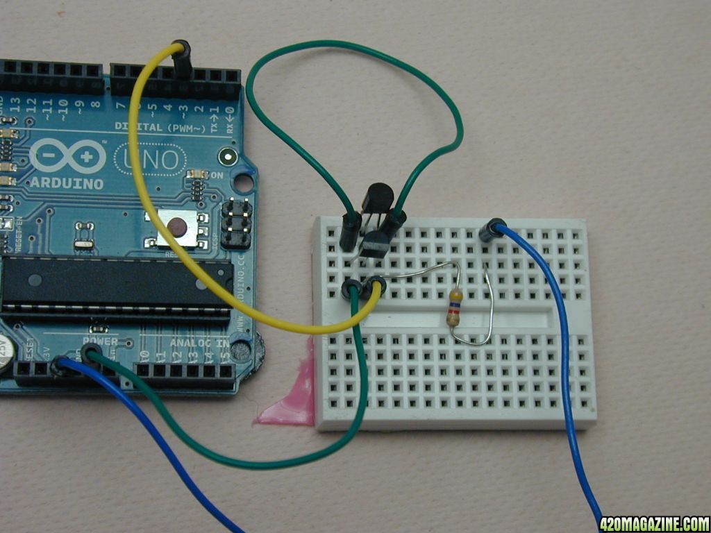
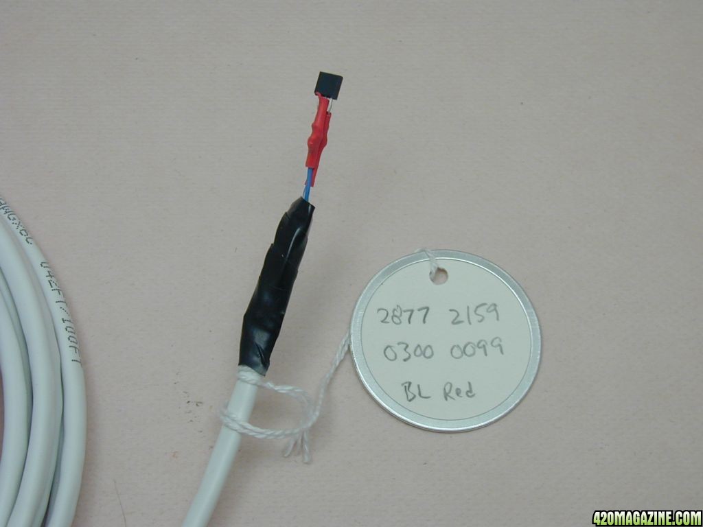
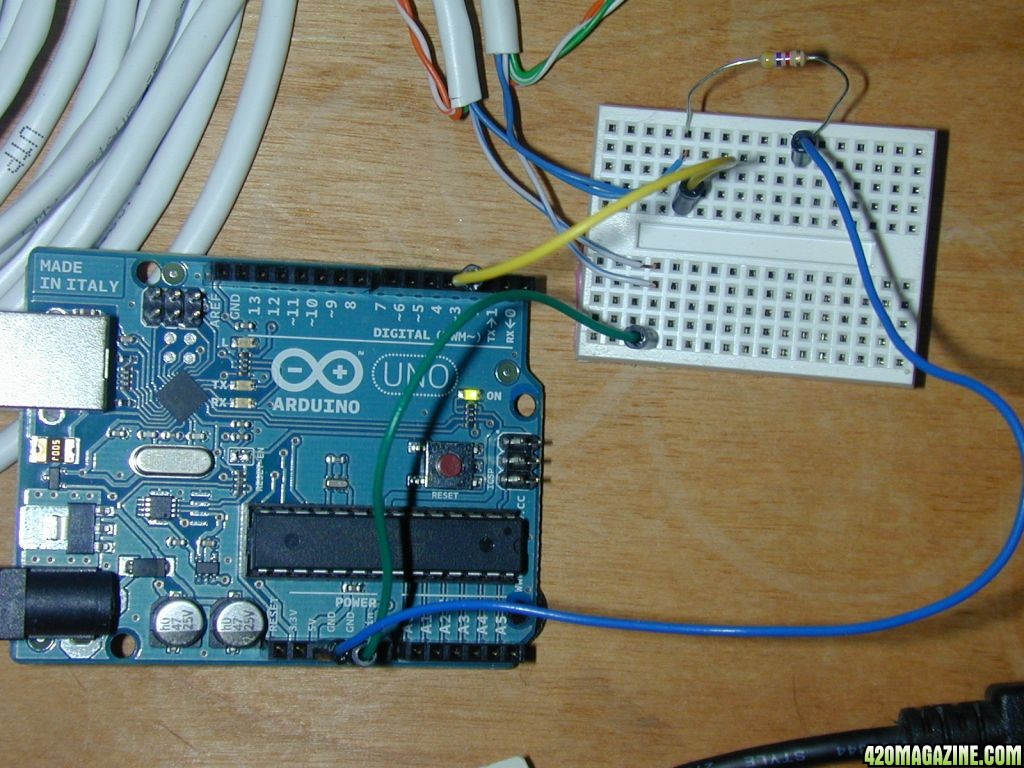

LESSON 2 Digital Temperature Sensors