

Skybound
Well-Known Member

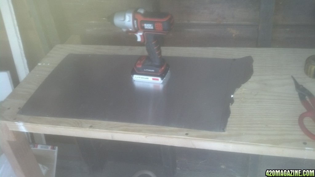
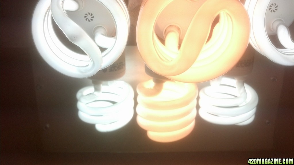
This is the CFL reflector I built the other day. It is a wing design and holds 6 CFL bulbs. What i am using is the 2nd revision of the second build. The first was complete disaster, and the second was designed great, but I failed to consider the length of my power strip and also the thickness of the 2 3/4" chassis before I cut the aluminum sheeting, but once completed, this reflector works flawlessly.
Materials needed;
24" length of aluminum flashing. Width must be equal or greater than your reflector depth
14"x14" square piece of 3/4" plywood
1 5/8" drywall screws
#6 x 1/2" wood screws (silver colored) 98 cents @ WallyWorld
1 - Power Strip
3 - Outlet to Socket Light Plug
3 - Twin Socket Lamp Holder Adapter
Optional Zip Ties
Tools Needed;
Circular Saw or Table Saw
Jigsaw or Coping Saw
Tin Snips
Impact driver or Screw Gun or Phillips Screwdriver
Drywall T-Square
Speed Square (carpenter's Square)
Measuring Tape
4" Grinder w/ Cuttoff Wheel or aluminum break
Automatic Center Punch
C-Clamp or Quick Grip
Drill w/ Drill bits
1.5" or 1.75" Hole Saw
Rasp or planer
Metal File
Safety Glasses
Before I get into this, I wish to stress that anyone attempting to build one of these should have at least some basic fabrication skills and a decent assortment of power tools.
My power strip is 11" long, so I designed my reflector with that in mind. Originally I intended for the strip to mount between the 2 chassis', but a mismeasurement lead me to cut the aluminum to 11" w/o including the extra 1.5" for the thickness of the 2 chassis @ 2x3/4". So I had to cut slots into the apex of the chassis to fit the power strip and the 1x1 that it is mounted to and this worked just fine.
First, unroll the 24" length of aluminum flashing and screw it down to a workbench or scrap piece of plywood. While you layout and construct the other parts, this stretching will uncoil the flashing considerably and it will be less difficult to work with once cut out. You will only need 18.5" in length, so don't worry about ruining the corners.
Next, layout where the holes will be located. These measurements must be taken from your power strip. Plan which outlets you will be using and do a dry fit of all sockets and bulbs to make sure they have enough room so you can change out bulbs when needed. Measure in from one end (remember which end) to the center of your first socket. Then measure from that center, to the next center, and again to the 3rd outlet center. In my case, the center to center to center were all the same, but this might not be so for every power strip so make sure!
Here are the measurements I used for the reflector bends. I purposely left out the measurements for the hole spacing so as not to confuse the DIYer. Apply the measurements you have taken from your power strip dimensions to the below draft;
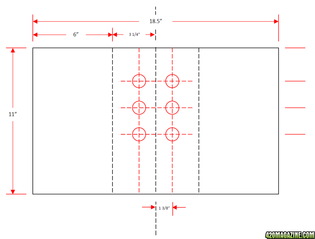
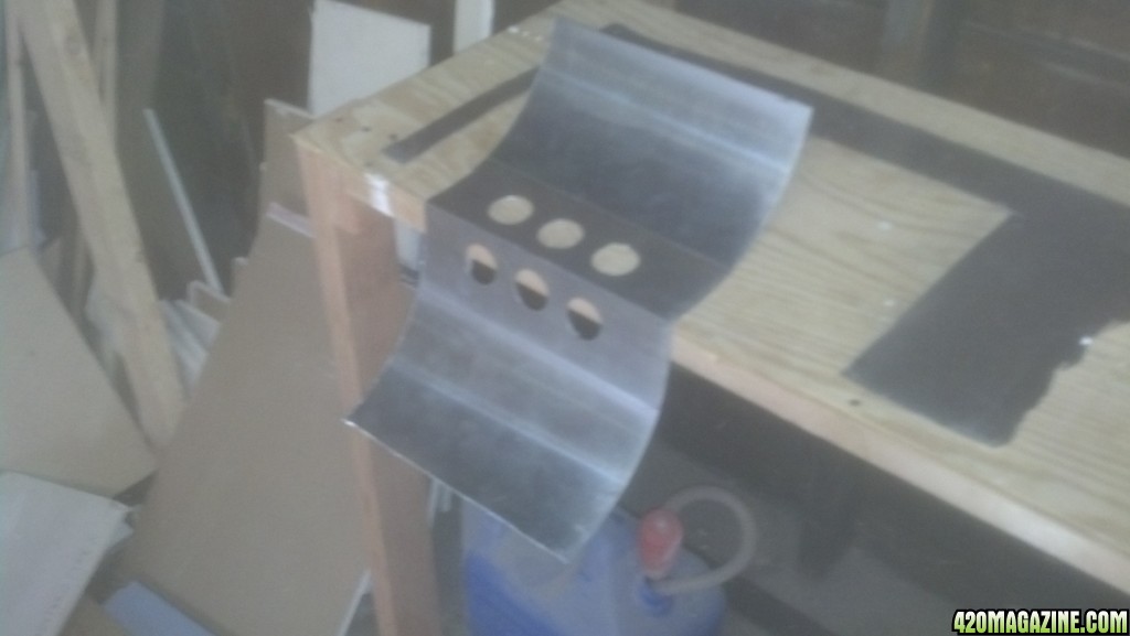
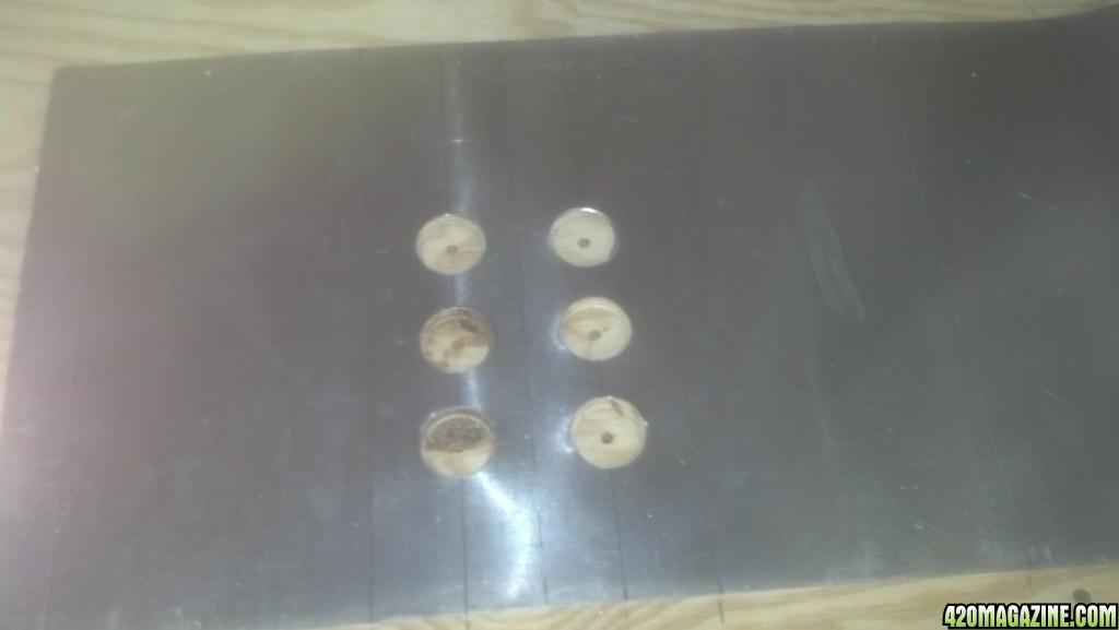
The internal red lines are construction lines only, used to locate the centers of each hole. Use a pencil or marker directly on the aluminum skin to locate your centers. Use the automatic punch to ping an indentation on those centers. Then use a hole saw to cut the holes. Ensure you get as many burrs as you can with the hole saw as they can easily cut you later and nobody wants a trip to the ER for a laceration. Next, plot where your creases will be. This is depicted with the internal black lines above. With the drywall T-Square (or equivalent), from the factory true edge of the aluminum, locate your markings for you creases and mark your 3 lines. then take your automatic punch and deeply scribe those lines. When bending later, this will create weak points in the metal and that will succumb to the bending pressure first creating a straight edged bend.
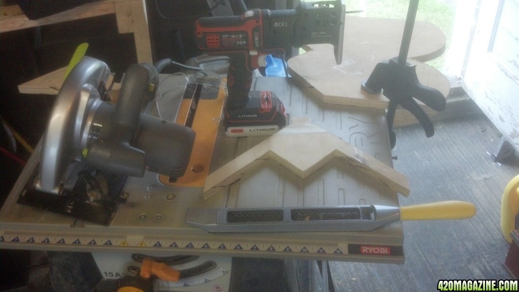
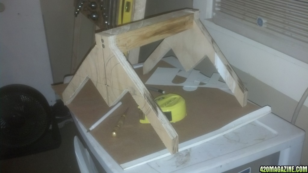
Now onto the chassis of the reflector. Cut the 3/4" plywood into 2 pieces measuring 7 x 14. cut the 7x14 down to 6x13. Measure into the 13" length to center @ 6 1/2" and pencil in your center line. From the side lower corner, use the speed square to make your 45° mark up towards the center line. Make this line 6". From that point, again with the speed square, 90° downward to center, mark a line to measure 3 1/4". Once done, you should be right on your center line. If not, adjust accordingly to make it work (fabricate). Repeat the process for the other side. This is the under side of the reflector and is where the aluminum will be mounted to.
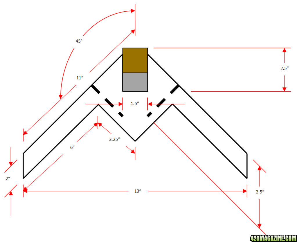
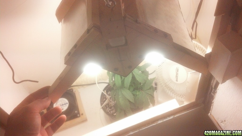
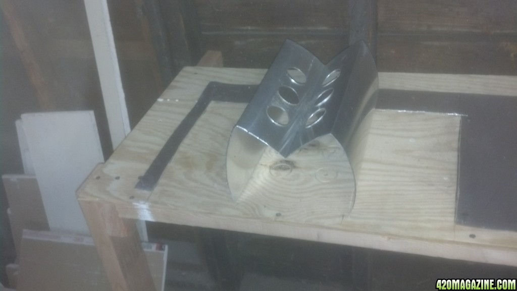
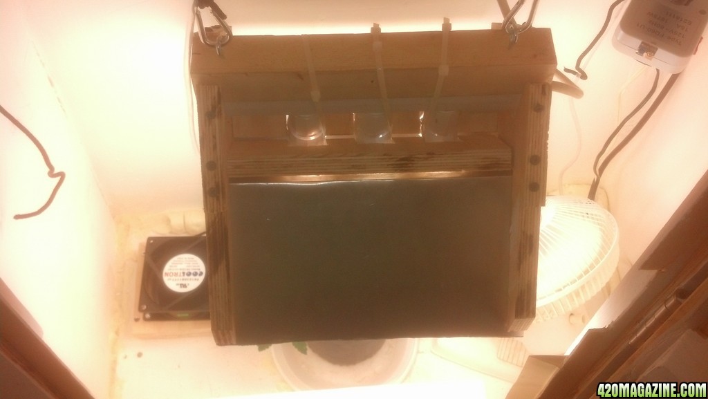
From the side lower corner, measure up 2". This is the thickness of the rib that the aluminum will screw to. From that point, 45° line all the way to the top center (It should measure roughly 11"). Repeat for the other side. From the center line, measure out each way by 3/4". Mark lines parallel to center all the way down to bottom of board. The space in between should be 1 1/2". This is where your power strip will fit in and the 1x1 block of wood it is mounted to. Please note, that if your power strip is longer than 11", the aluminum piece must also be equally deeper. A piece of 1x1 actually measures 1 1/2" x 1 1/2". Add the thickness of your power strip (mine is an additional 1 1/4"). 1 1/2" + 1 1/4" = 2 3/4" deep. This is where a little trial and error comes into play. It is important to find the exact plane that your power strip can be set at that the light sockets will meet the aluminum. You may allot for a 1-2 mm tolerence, but keep in mind that the closer to the aluminum your sockets get, the more the placement of your holes in the metal will veer away from being centered to each socket. So I suggest cutting your notches a little at a time. If need be, you can always raise your power strip slightly away from the aluminum bringing your hole to socket alignment closer to true. Once you find your alignment, you can fasten each side of the chassis notch to the 1x1 with a drywall screw. I strongly suggest when screwing into the plys of the plywood, to always drill a slightly smaller hole than the diameter of the screw. If not, the plywood will split. The below picture shows a side view of my reflector in operation. Initially, I made the ribs too thin and had to add some plywood pieces to thicken the mater I needed to screw into. This tutorial already keeps that in mind and plans for 2" ribs instead of 1".
Once the chassis are cut and the frame is built, now it's time to cut and bend the aluminum. In a previous build (failed miserably) I cut the metal with snips. This was very messy and getting straight lines was impossible for me. This time I used my 4" grinder with a cutoff wheel. this made great lines and I was also able to remove many of the burrs with the wheel afterwards. Once the 18.5 x 11<--(this is the length of your power strip) is cut out, it will roll up slightly. Locate the enter scribed mark and position it over the corner of your work bench or table. Slowly work the metal to fold exactly on this line. You may have to apply pressure to multiple points at gradual intervals to achieve this. Keep working it till you have a 90° bend or slightly greater.
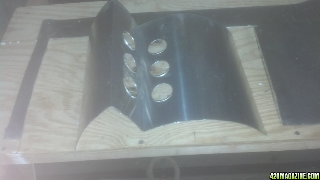
Flip the metal and find the other 2 scribe marks. If you applied a good amount of force when scribing the lines, you should see feint lines on the other side. Position a line over the corner of your table and repeat the above process. then do that same thing again for the remaining line. You should be left with an EM shape of metal.
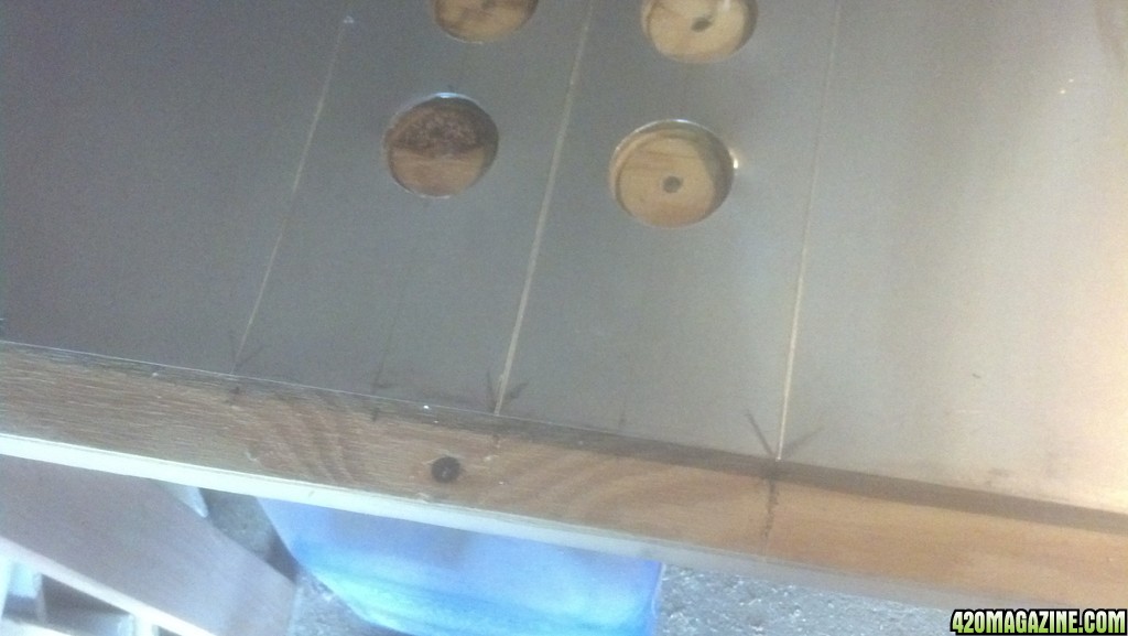
Now that you have the metal all cut, and the frame cut and constructed, you can now build your reflector. Place the metal skin onto the corresponding lower side of the reflector. You may have to make minor adjustments/bends to get everything to align. If everything is near true, you can begin to screw the aluminum to the chassis. You want to begin screwing the metal down in between the 6" facet and the 3 1/4" facet first. Before screwing, get your center punch and ping a center hole. This will ensure your drill bit does not slip away while drilling. Only do a single hole at a time as screwing the metal down will cause it to shift slightly and you will have to pull it back into alignment later. Find a drill bit that is slightly thinner than the #6 screw. Drill a hole through the metal and about a 1/4" into the wood. Then screw in the screw. Use a screw driver so as not to over torque it. Also do one side of the reflector on both sides of center before moving to the other side. Once on the other side, you will likely have to pull the wood a bit to get it into alignment with the metal skin. Once you have your alignment, you may have to manually hold it into place while you carefully punch and drill, then once your screw is in, you can let go. Then repeat for the other side of the center till you have what looks like this;
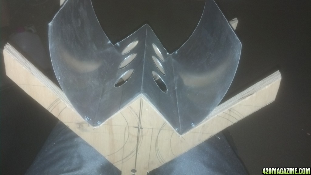
Then simply begin working your way towards the outer edges. I did not see the need to screw down towards the center beyond the single screw I used on the 3 1/4" facet, but that's up to you.
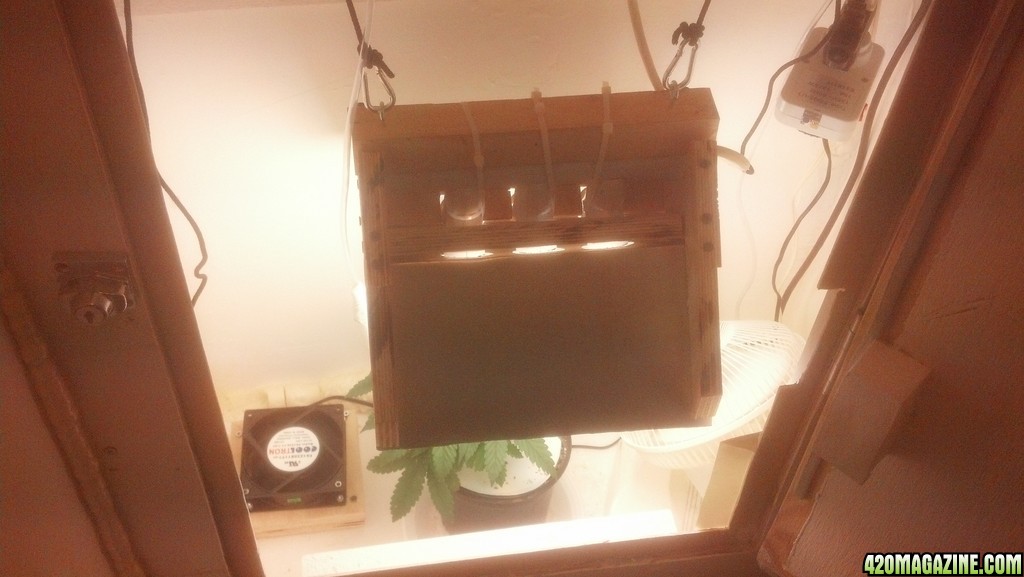
I then secured the socket parts to the power strip with zip ties. This is optional. However, doing this caused my sockets to pull out of alignment and I did not want the bulbs to contact the metal, possibly shorting out a circuit, so I build a comb like concoction that I was able to slip down into the back of the reflector to hold the sockets in place and I then screwed that bracket into place with drywall screws.
I hope this will be helpful to somebody. I also have an HID, but circumstance dictate that I use CFLs for now, so I had to build a reflector. Here are some more pics I took during the build. I originally shot for another design, but had to make last minutes adjustments in the middle of the night. The above is planned to accommodate for all that.
")


