MisterPeabody
New Member
When I decided to give indoor another try, It had to meet certain criteria. First and foremost it had to be stealthy. It had to be able to support the full life cycle of a plant through maturity. Knowing very little about cab design, yet being a "jump in with both feet" kinda guy, I settled on a rudimentary set of plans and set out to find the building block of my dreams
From there I began a search for the perfect cabinet (as if there is such a monster), but it first must at least have the potential. First on the list is the ability to light proof without a huge mess of redesigning. Once I found said cabinet, then began an education such I could never receive in any school or university. This is where I began. Enjoy.
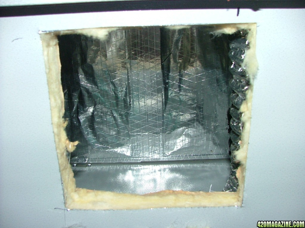
The first order of business is to decide where to locate the main blower. Since the house has a crawlspace, and because of noise, it was decided to put a 170 cfm inline turbine fan in a Rubbermaid tub for sound control. Now to get the 4" return into the cabinet from the crawlspace. I carefully drilled a small pilot hole and adjusted it to be able to get a 4.5" hole through the floor, and have it lined up properly with the lower floor of the cabinet
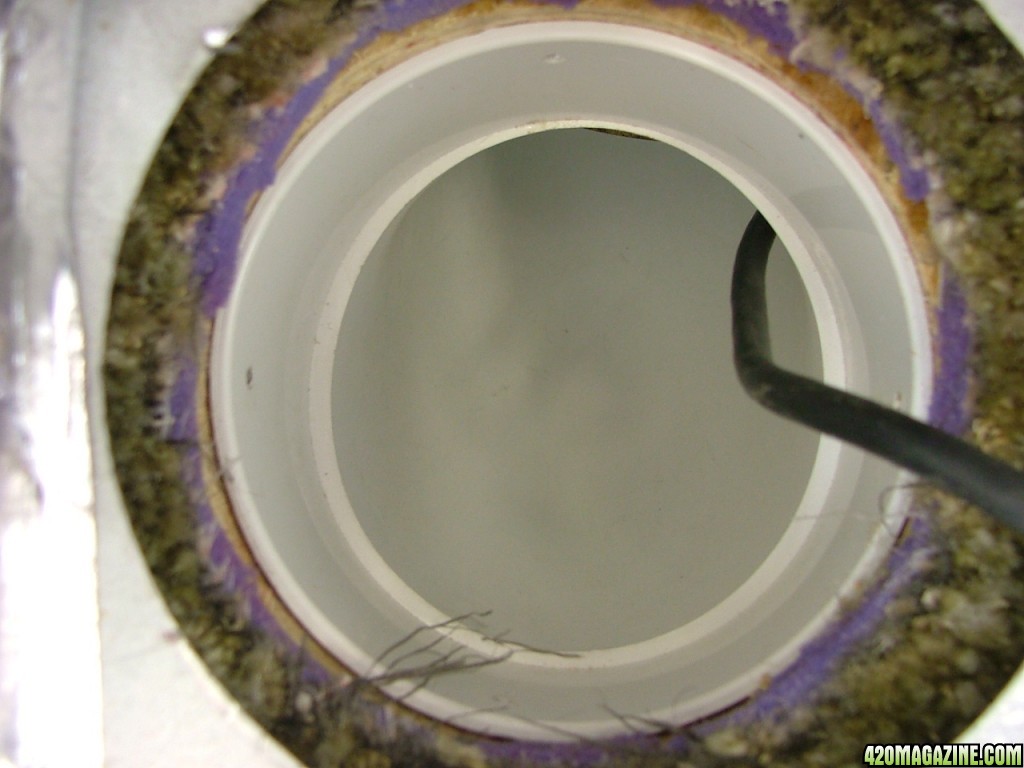
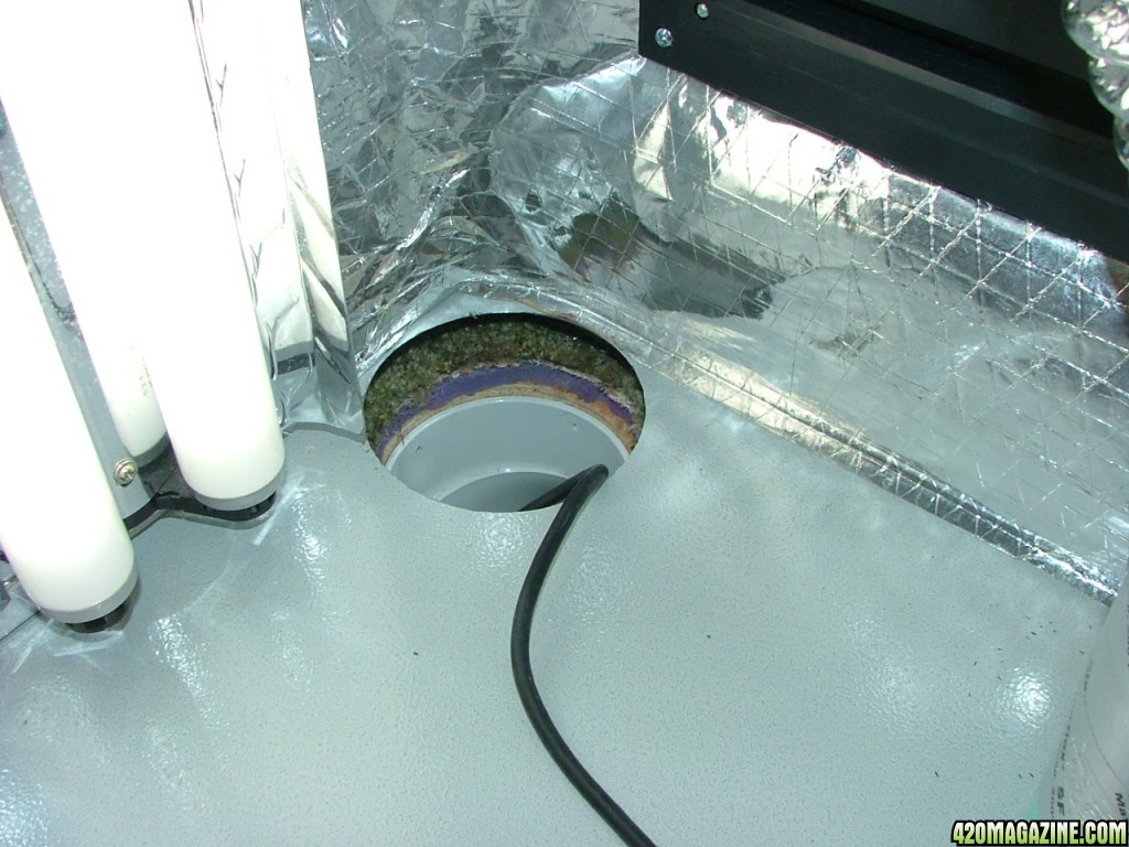
Here you can see the hole in the cabinet, the carpet cut out, floor cutout as well as the 4" PVC elbow. The one cord exiting is the power cord for the inline turbine fan. I want to have control of it in the cab, as I plan on wiring in a 5 amp ceiling fan control, allowing me to speed up or slow down the fan from in the cab.
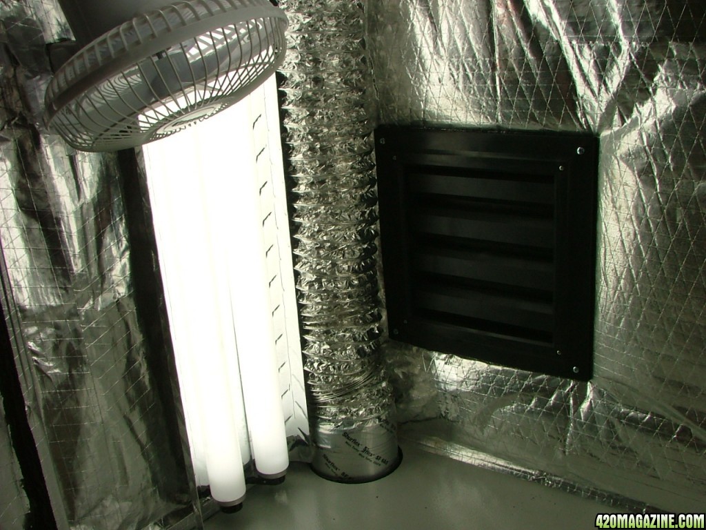
Time to install the rear 10" passive darkroom register. (I don't have pictures of it, but before deciding to add this in the lower cab, I only had a 6" passive return. The first time firing up the fan, when I went to close the doors, they almost smashed my fingers sucking it shut). I needed still more return.
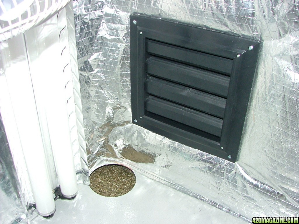
Note the 4" T-12's on left and right side of cabinet. Hey! They worked in the 70's!
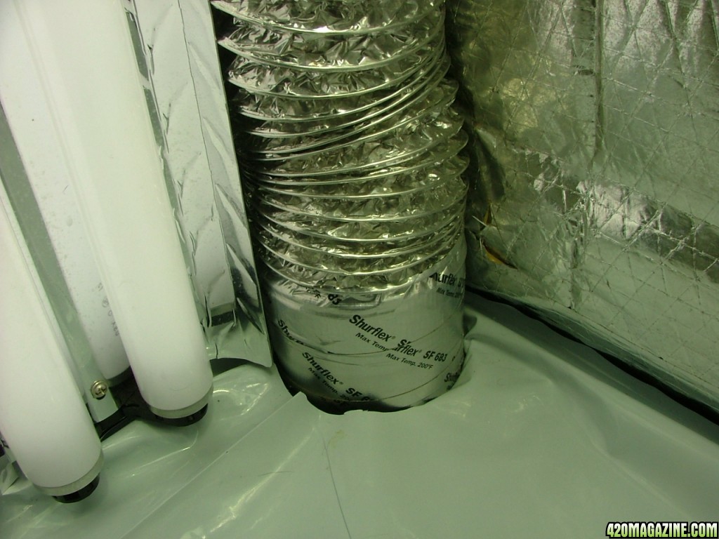
This shows the 4" PVC section that will seal the airflow from the 4" PVC 90 located in the floor. From this to 4" flex hose (dryer vent) to be distributed into the cabinet
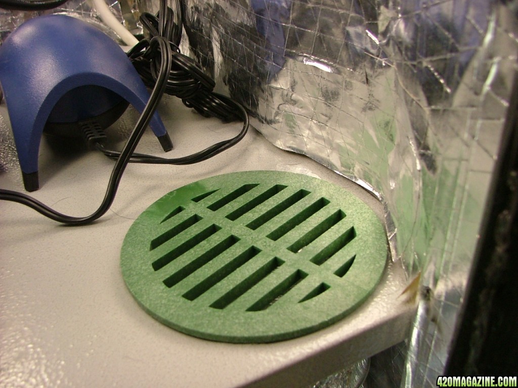
Gotta love the hardware store. 2 bucks. and a neat way to prevent losing whatever could fan into a 4" hole and get pulled into a fan
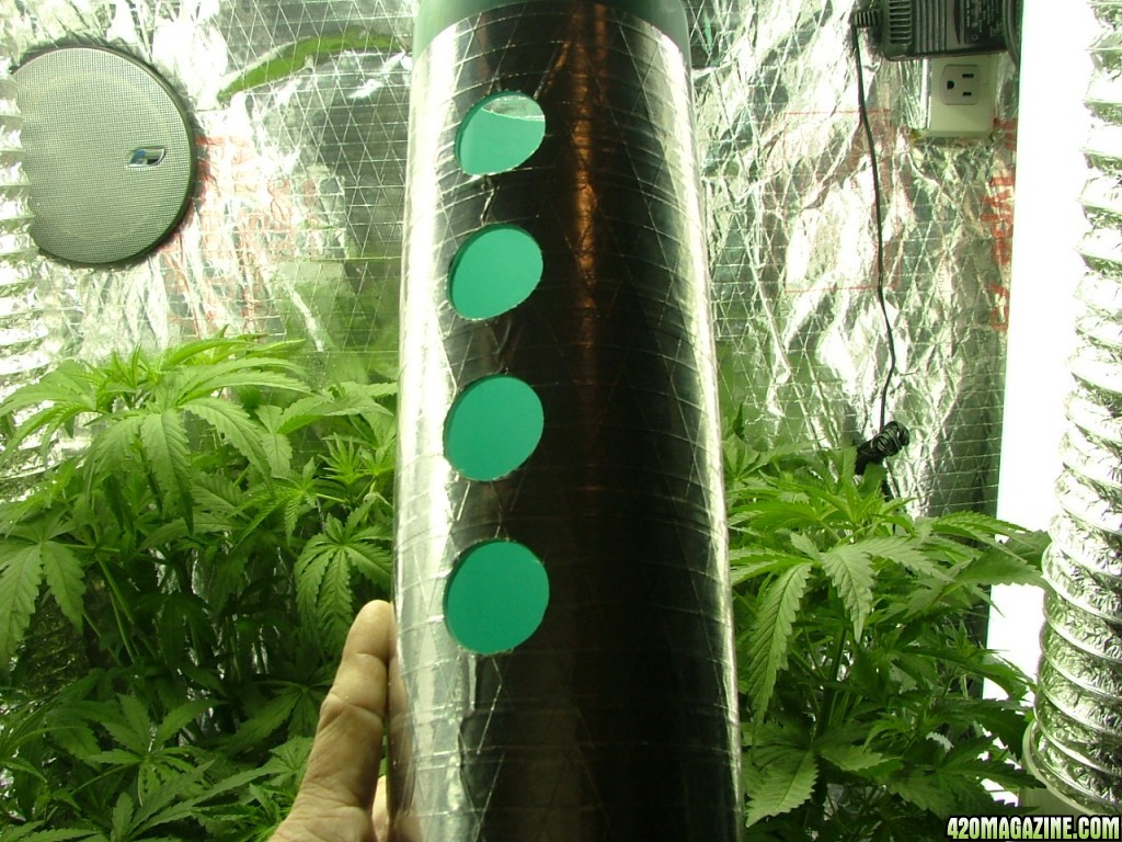
Here is a photo of what I am using to kill odors. I drilled holes into it, capped the bottom and tied it into the return of the upper cabinet. Indecently, an ONA 1 qt jar will fit PERFECTLY into the 4" PVC. Remove the cap, and the air pulling into the 4" PVC draws MORE than enough ONA to kill even the most stubborn odors

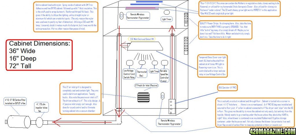
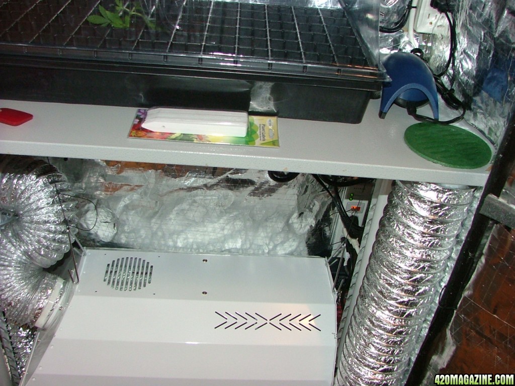
This view shows how the airflow moves through the cab. It draws in at the right side of the cab, into the upper cab that is light isolated from the lower area. From there it is drawn back to the left side of cabinet and back down to the fan located in the crawlspace
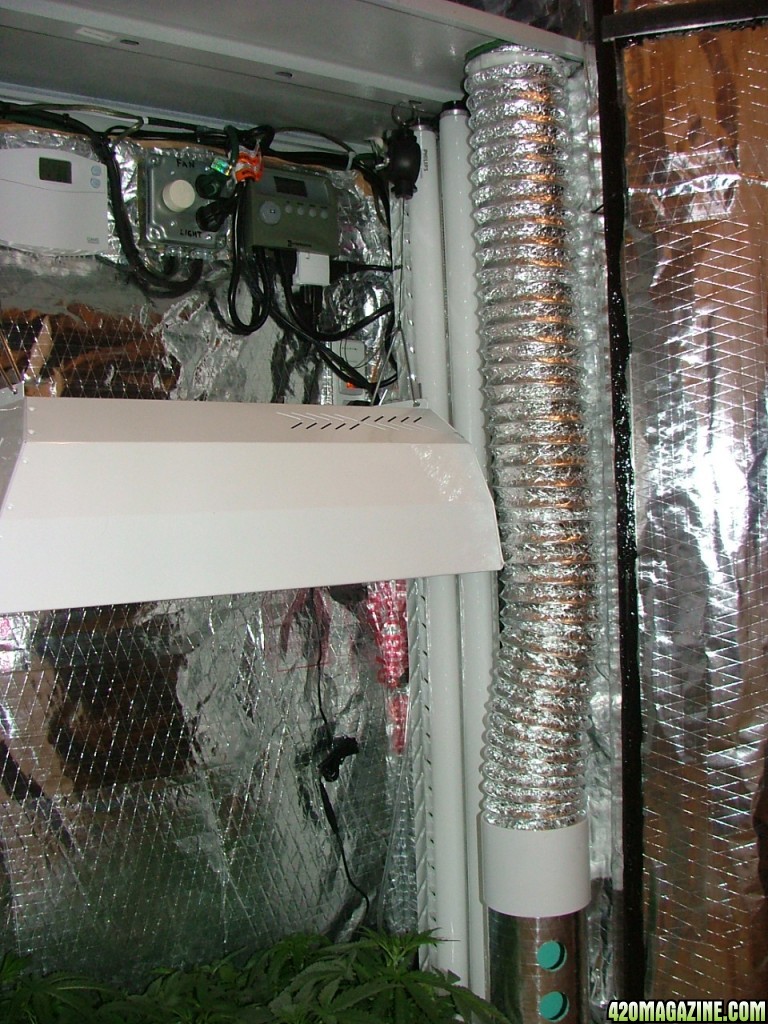
Here's a view of how the light is vented. This hood was a 250 watt with ballast built in. This was short lived, as the cap start ballast is noisy and creates too much heat.
A better view of how the light vent ties into the upper cab via a 4" T. This design has worked well and the airflow concept was kept throughout the design/redesign cabinet series, though fined tuned along the way
View of the completed first design cabinet. Looking back, I can see many errors in this design, however through trial and error, I have been able to improve this design considerably, and it has been a fun ride as well as an educational one. Hope you enjoyed! Time for Mr Peabody to sit back and enjoy the fruits of his labor...
From there I began a search for the perfect cabinet (as if there is such a monster), but it first must at least have the potential. First on the list is the ability to light proof without a huge mess of redesigning. Once I found said cabinet, then began an education such I could never receive in any school or university. This is where I began. Enjoy.
The first order of business is to decide where to locate the main blower. Since the house has a crawlspace, and because of noise, it was decided to put a 170 cfm inline turbine fan in a Rubbermaid tub for sound control. Now to get the 4" return into the cabinet from the crawlspace. I carefully drilled a small pilot hole and adjusted it to be able to get a 4.5" hole through the floor, and have it lined up properly with the lower floor of the cabinet
Here you can see the hole in the cabinet, the carpet cut out, floor cutout as well as the 4" PVC elbow. The one cord exiting is the power cord for the inline turbine fan. I want to have control of it in the cab, as I plan on wiring in a 5 amp ceiling fan control, allowing me to speed up or slow down the fan from in the cab.
Time to install the rear 10" passive darkroom register. (I don't have pictures of it, but before deciding to add this in the lower cab, I only had a 6" passive return. The first time firing up the fan, when I went to close the doors, they almost smashed my fingers sucking it shut). I needed still more return.
Note the 4" T-12's on left and right side of cabinet. Hey! They worked in the 70's!
This shows the 4" PVC section that will seal the airflow from the 4" PVC 90 located in the floor. From this to 4" flex hose (dryer vent) to be distributed into the cabinet
Gotta love the hardware store. 2 bucks. and a neat way to prevent losing whatever could fan into a 4" hole and get pulled into a fan
Here is a photo of what I am using to kill odors. I drilled holes into it, capped the bottom and tied it into the return of the upper cabinet. Indecently, an ONA 1 qt jar will fit PERFECTLY into the 4" PVC. Remove the cap, and the air pulling into the 4" PVC draws MORE than enough ONA to kill even the most stubborn odors
This view shows how the airflow moves through the cab. It draws in at the right side of the cab, into the upper cab that is light isolated from the lower area. From there it is drawn back to the left side of cabinet and back down to the fan located in the crawlspace
Here's a view of how the light is vented. This hood was a 250 watt with ballast built in. This was short lived, as the cap start ballast is noisy and creates too much heat.
A better view of how the light vent ties into the upper cab via a 4" T. This design has worked well and the airflow concept was kept throughout the design/redesign cabinet series, though fined tuned along the way
View of the completed first design cabinet. Looking back, I can see many errors in this design, however through trial and error, I have been able to improve this design considerably, and it has been a fun ride as well as an educational one. Hope you enjoyed! Time for Mr Peabody to sit back and enjoy the fruits of his labor...

 for the comments! It's been a lot of fun. I'm starting a new grow, and will be sure and post progress.