HELP! HPS wiring

RaoulDukeHsT

New Member
I recently got this 150 watt HPS Lamp, however upon setting it up i realized there was some wiring to do.
I've been scowering sites for a few days to find a diagram but no luck. Does anyone here have any ideas of the wiring of this set-up.

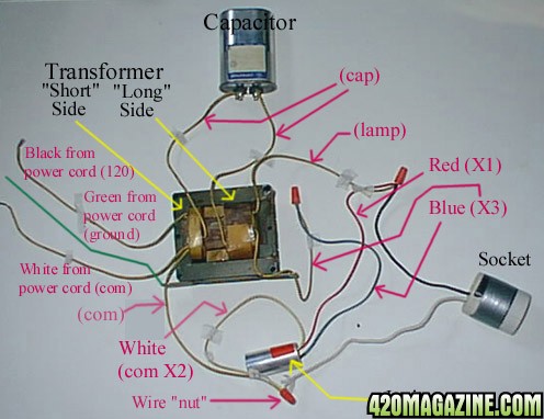
Theres a capacitor of sorts that has 3 wires that are not hooked up, RED, BLUE, BLACK.
There is one GREEN wire. (i assume this is ground)
There are 2 wires coming outta the socket itself they are WHITE and BLACK.
When the boxs is closed up only the black(from socket),white, and green wire are out of the box.

Basically i need to know where do the wires from this capacitor go or which wires do i connect to them?

HOW DO THESE CONNECT????
 
High Pressure Sodium (HPS)
This wiring description is for an advance brand ballast. If you end up with a different brand and the wiring doesn't seem quite the same, then it isn't. But should not be very difficult to figure out the difference after familiarizing yourself with the various wires and parts in the illustrations.

First, orient the transformer so that you know which side is "long" and which is "short". Locate the 2 wires that say "cap" on them. They should be coming from the inside of the transformer bulges. These wires all either get connected directly to the capacitor using connectors or by soldering, or with wire nuts to the wires coming from the capacitor.

Next, locate the wire coming from the long side of the transformer which is labeled somewhere with the number 3(or "X3"). Then with a wire nut, connect it to the number 3 wire coming from the ignitor. Make sure the nut goes down snugly and that no bare wire can be seen.

Before going any further, you need to figure out how far from the ballast the bulb will be placed. In my example, the wires to the socket are only a foot long so that I could get it in the picture. In real life, the wires will usually be 6 to 10 feet long. Use a piece of heavy duty (extension cord) wire and wire nuts to extend the socket's wires as far as you need to. Just attach black to black, and white to white. The green wire is a ground which will get attached to your reflector on one end, and to the transformer base/ballast box on the other end to safeguard against shock.

Then, find the white wire labeled "com X2" (or "com2" or whatever it is in your particular case) coming from the transformer's short side, the #2 wire from the ignitor (it may also say "com X2" or "com2" or simply "2"), and the white wire from the socket. Connect all three of these wires together using a wire nut. Make sure the connection is tight with no bare wire showing.

Find the wire coming from the transformer's long side labeled "lamp". Along with the #1 ("X1" or "1") wire from the ignitor and the black wire from the socket. As above, connect all 3 wires together with a wire nut.

OK, you're almost done! The last two wires should come from the transformer's short side. One should say "com" and the other "120". These are the two wires that will go to your power cord. Cut the extension cord to the right size and trim away the outer insulation to expose the three wires (white, black and green).

The white wire gets connected to the "com" wire on the transformer, while the black wire goes with the "120" (or whichever voltage you have) on the transformer. The green wire is the ground and that gets attached to either the ballast box or the base of the transformer to safeguard against shock.

If you bought a multi-tap ballast, now is the time to deal with that. There should be a wire with a connector clip on it attached to 1 of 4 possible spots on the transformer. These 4 options are for 4 different voltages. Find the one labeled "120" (or whatever your voltage is) and attach the wire/clip to that one. Some ballasts simply have a few extra wires inside labeled for different voltages. In that case, find the one for your voltage and strip the insulation off the end, then connect it with a wire nut to the black from the power cord. Make sure to leave the other voltage wires with all their insulation. For safety's sake, cover each of the unused wires (individually) using a spare wire nut for each one to insulate them.

Hope this helps a bit,
Post the pic when I find it .....
 
Ther' ya go ...

faqfix2.jpg
 
this is very informative, however i lack an ignitor and capacitor, i think they are all in one with the transformer itself, as you can see in the pics i posted above. ill try and "cob" it up but im not too sure it will be successful. ill post if it is otherwise please post if you have any knowledge.
 
this is very informative, however i lack an ignitor and capacitor, i think they are all in one with the transformer itself, as you can see in the pics i posted above. ill try and "cob" it up but im not too sure it will be successful. ill post if it is otherwise please post if you have any knowledge.
 
Your light looks incomplete. I did not see the igniter or capacitor either.
Good luck, wish I was able to help but only have limited knowledge of buiding lights.
 
I could probably figure it out if I had it in my hands, but otherwise, I have no idea how it goes together.

May I ask why you bought a HPS that needed major assembly? May I ask why you bought only a 150w system?
 
i didnt buy it. the place i work was just gonna throw it away because they are replacing a bunch of diffrent lights for the building to have one uniform type of light and there was just 2 of these HPS so i snagged one. Its probably gonna be easier to just buy what i need anyway. Thanks for the help folks.
 
Back
Top Bottom