300w LED + Alien Blackberry Grow

Blue Garden

New Member
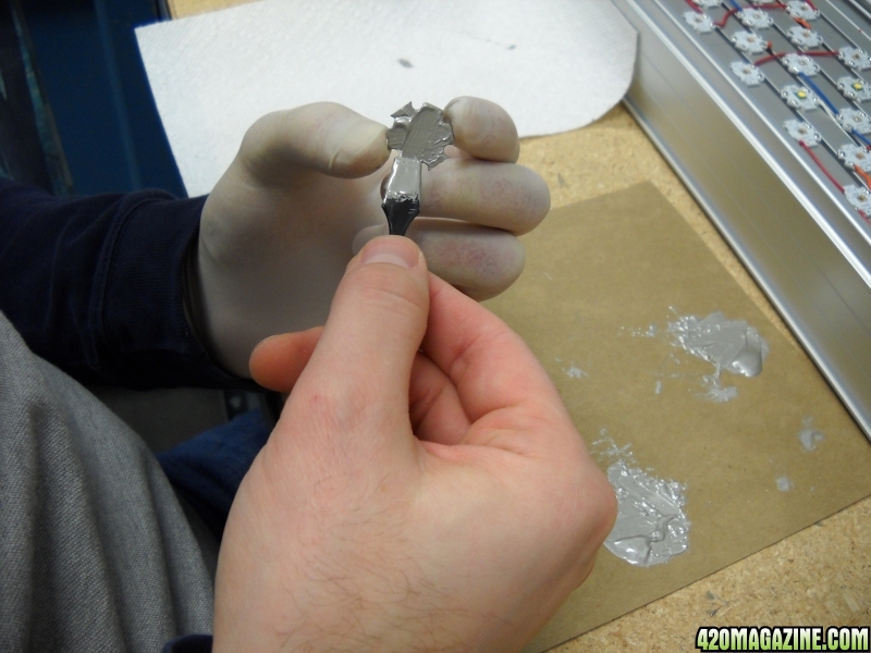
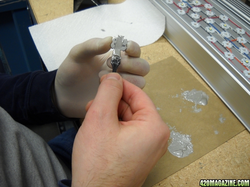
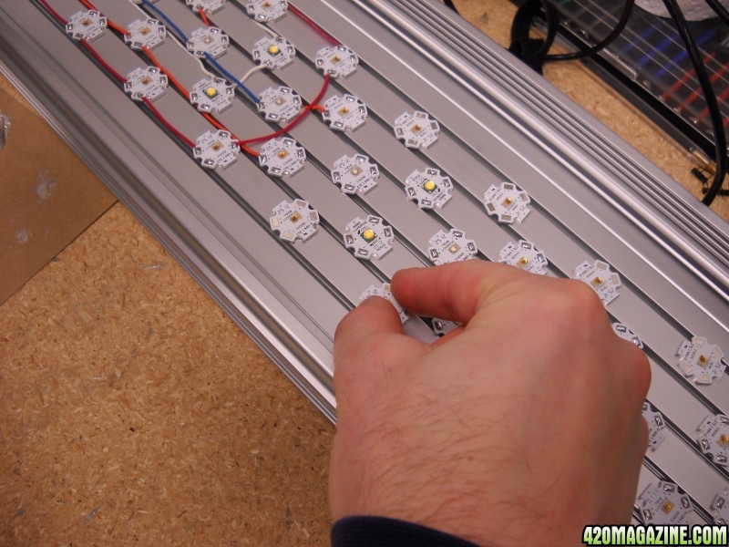
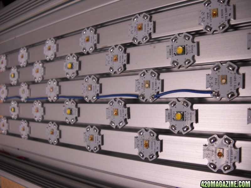
What up. Been lurking around the led threads and finally decided to do a grow thread with my new LED. I’ve been on the fence for a while and decided to take the leap after seeing some success with other peoples grow. After doing much research, I decided to get some quality parts instead of ordering the ones made in china. The Chinese fixtures are cheaper initially but who knows what is under the hood? Could be a sweet ferrari body with a kia engine lol. Anywho, on with the show. I decided to go with a shorter strain and chose the Alien Blackberry for that purpose. It finishes anywhere between 2.5-4’. Soil will be the grow medium. I’m curious how much yield will result from this light.

-This is a legal prop 215 grow-

This is what I will be working with
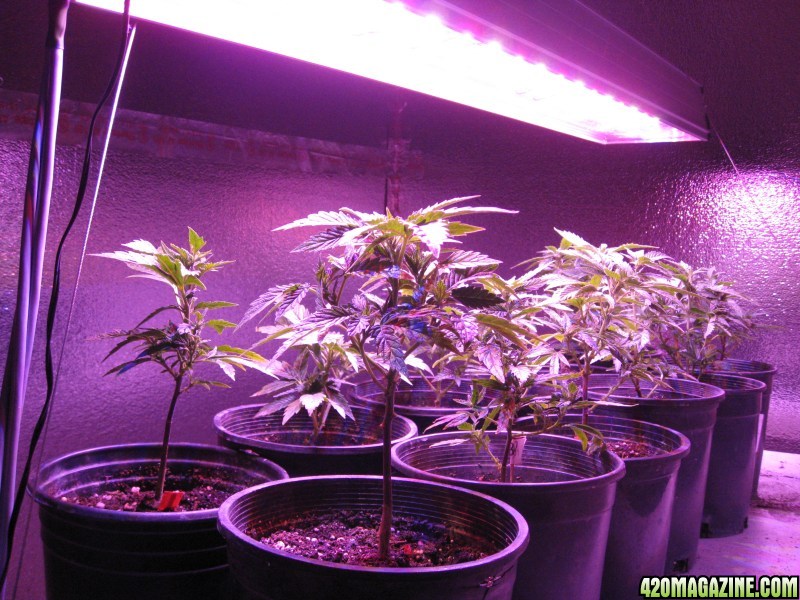
• 1” thick foam walls with reflective material
Shop 1-in x 4-ft x 8-ft Expanded Polystyrene Insulated Sheathing at Lowes.com
(originally was going with a tent but concerns with heat retention made me reconsider)
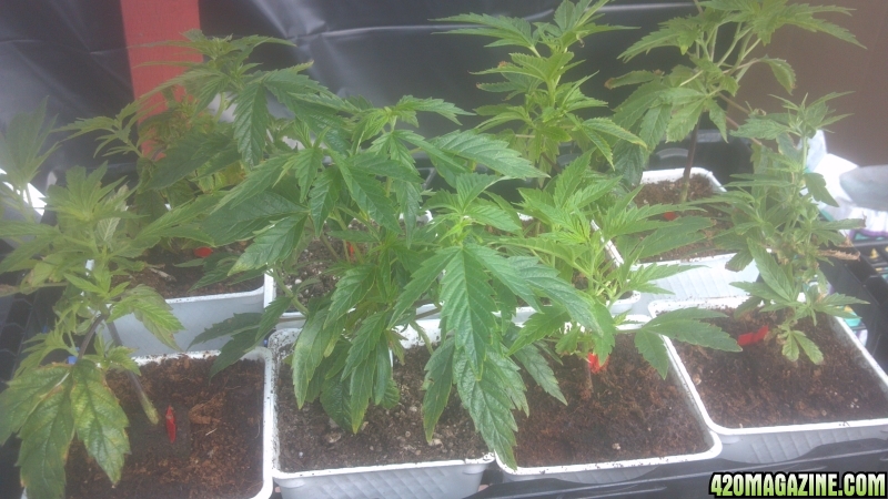
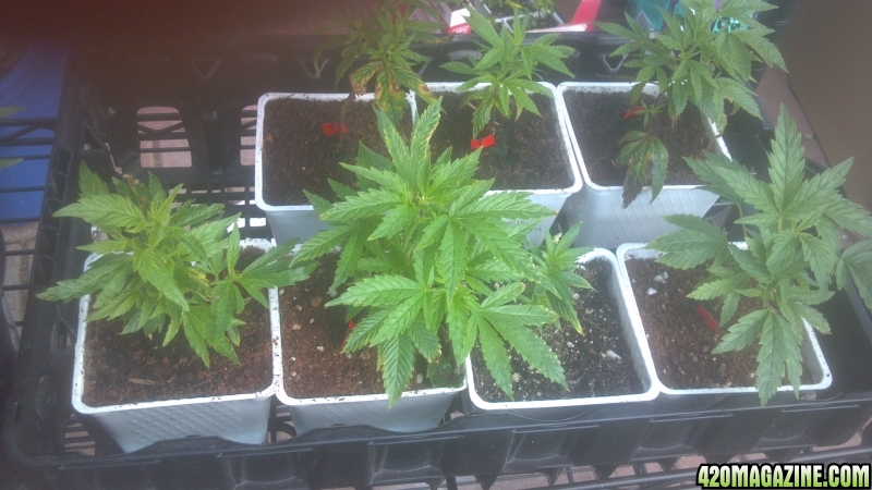
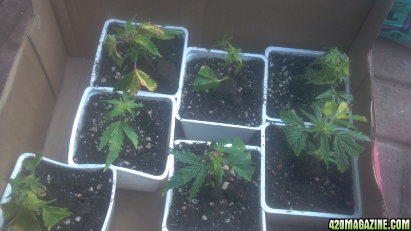
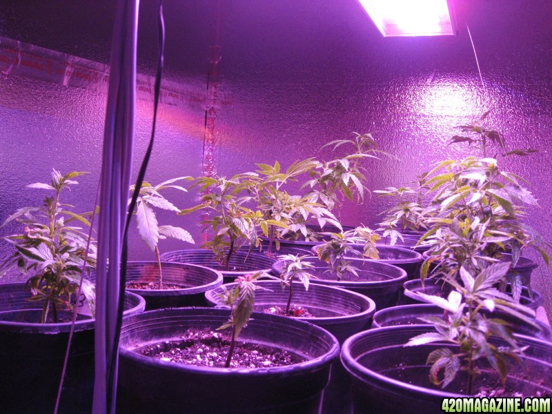
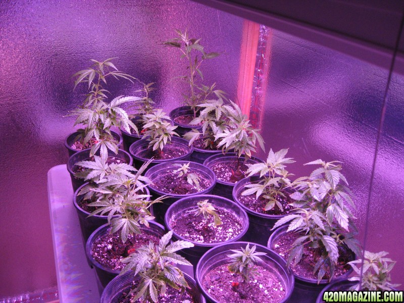
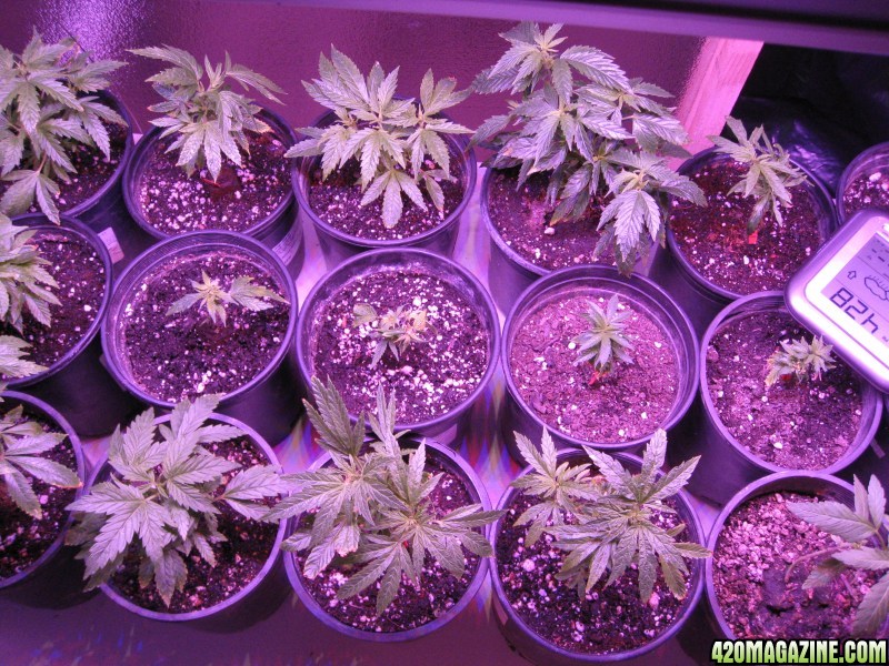
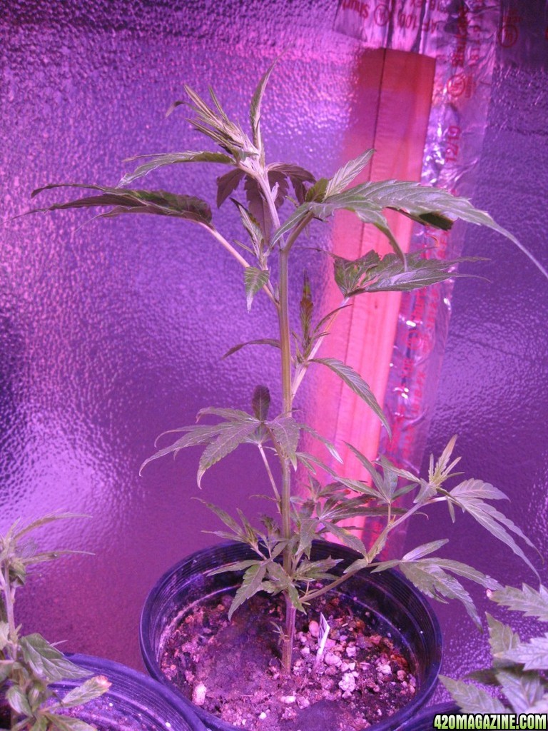
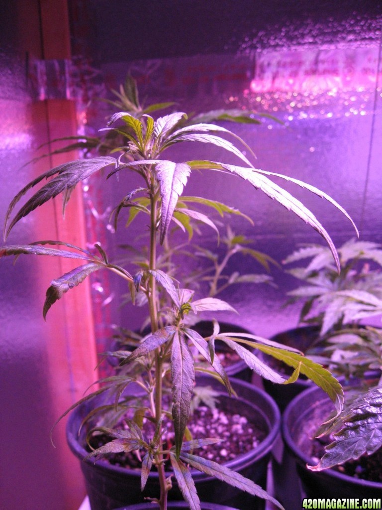
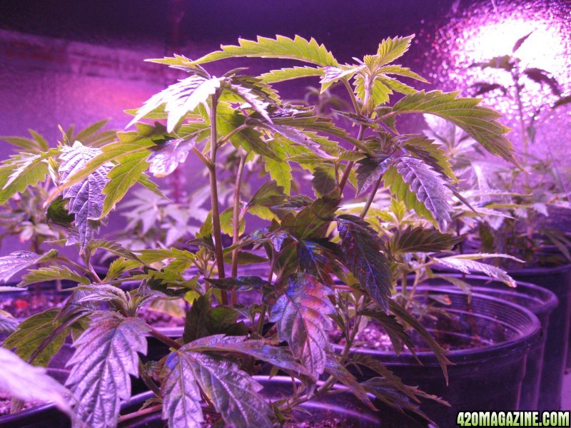
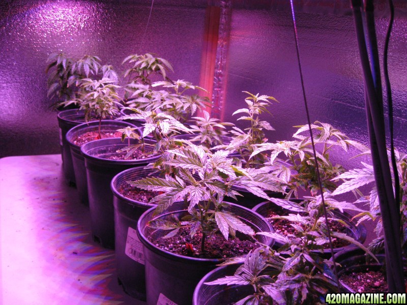
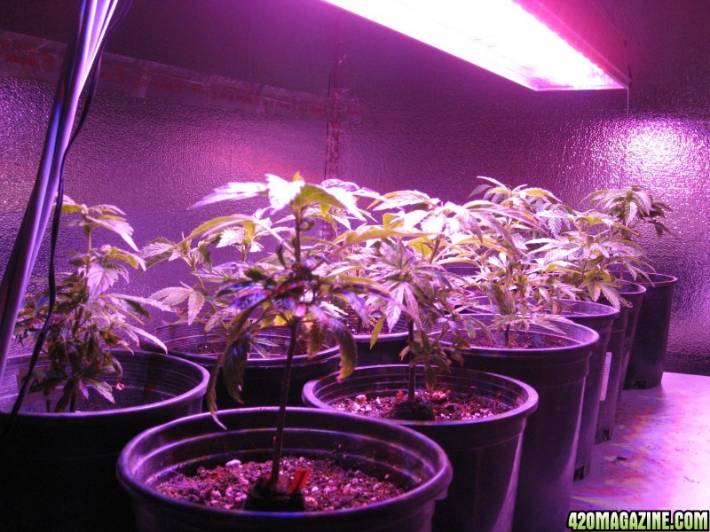
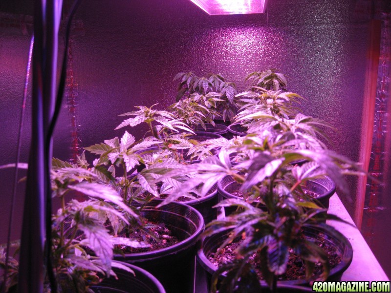
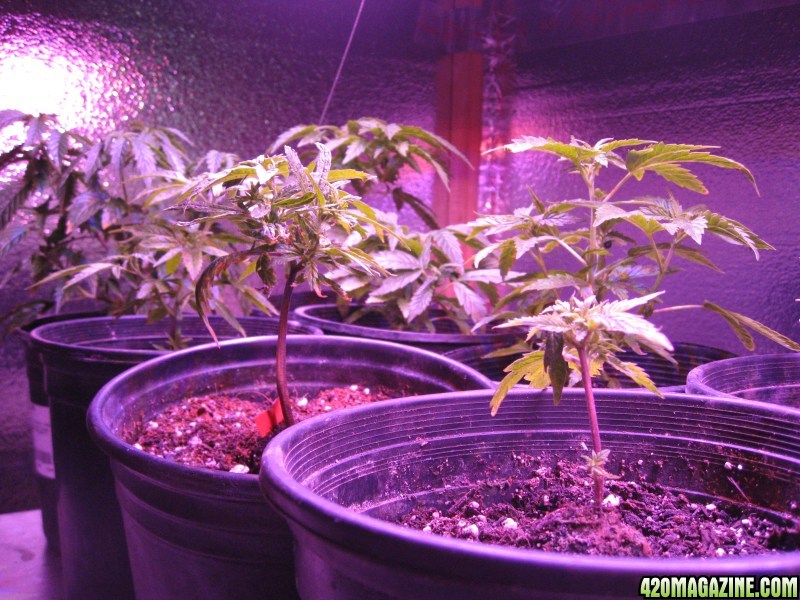
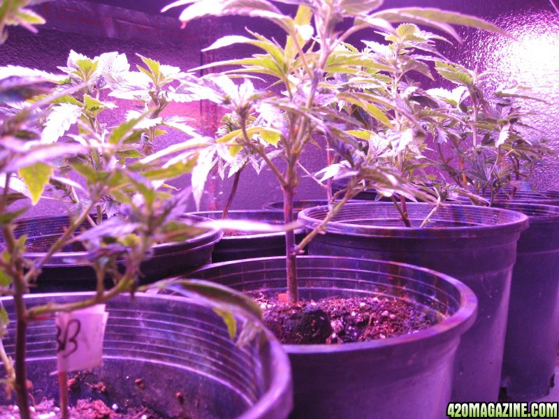
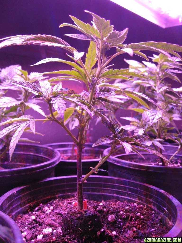
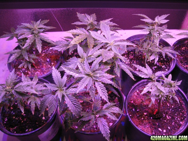
• 15 Alien Blackberry clones
• Soil
• 1 or 2 gallon pots
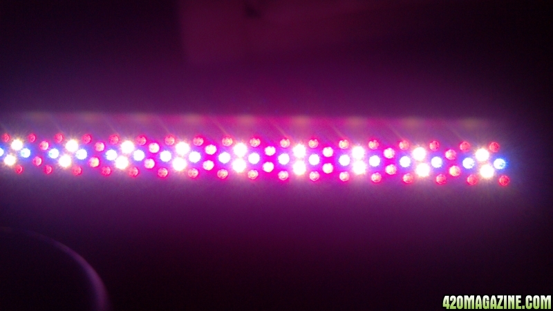
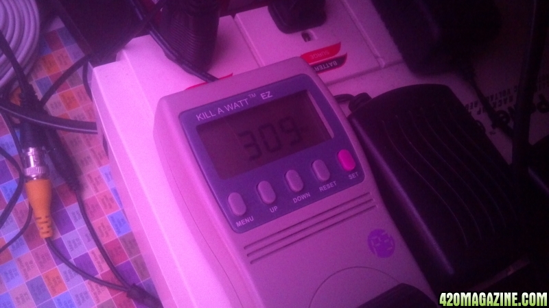
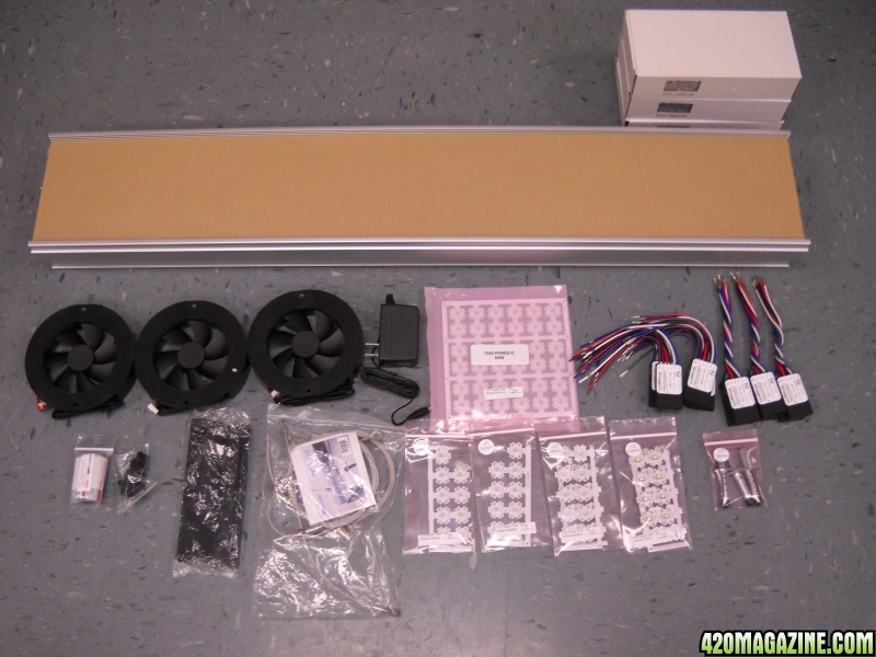
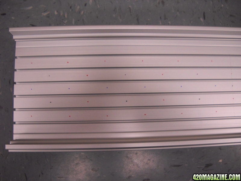
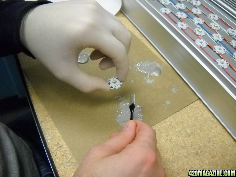
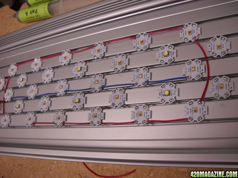
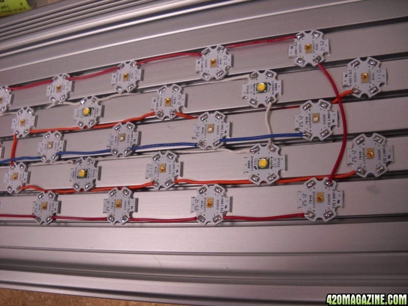
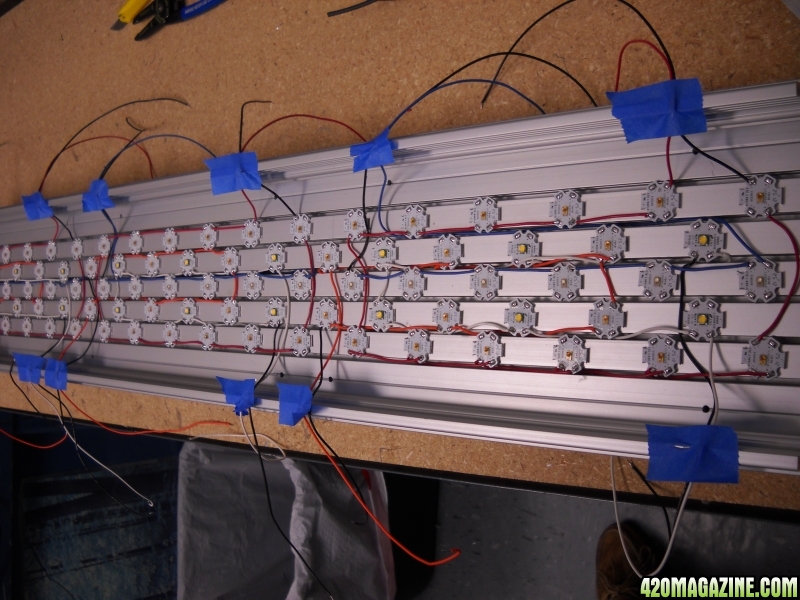
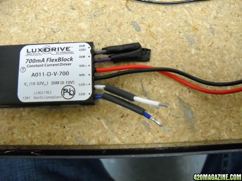
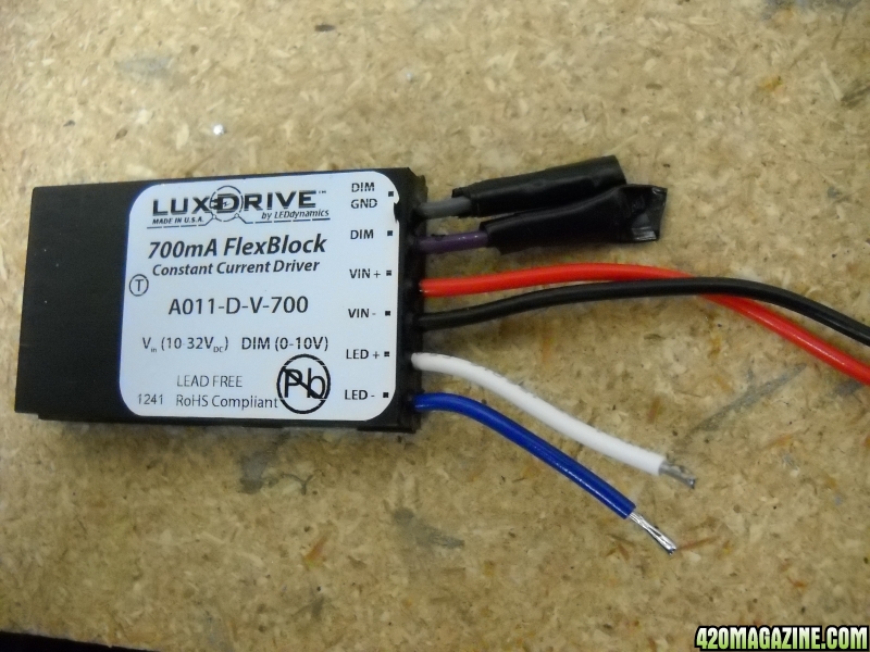
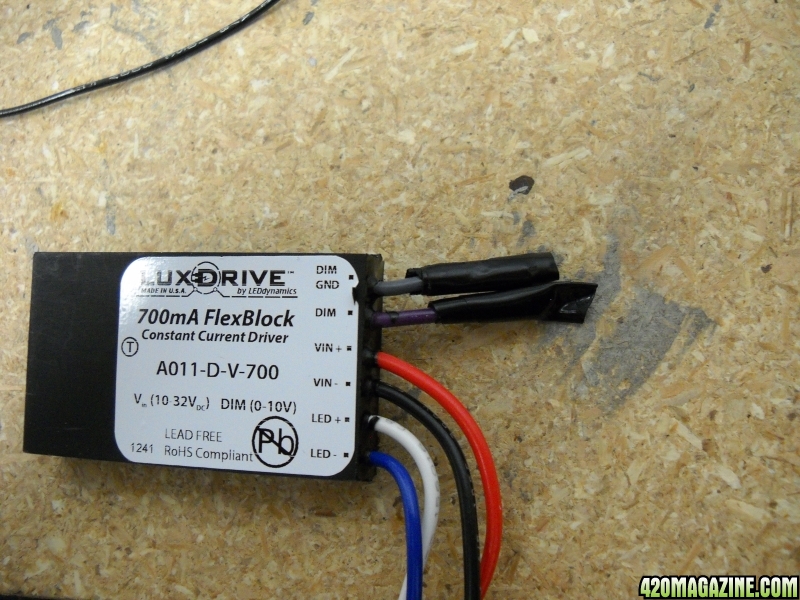
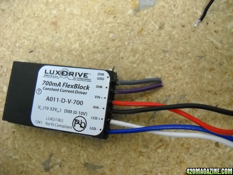
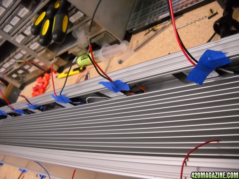
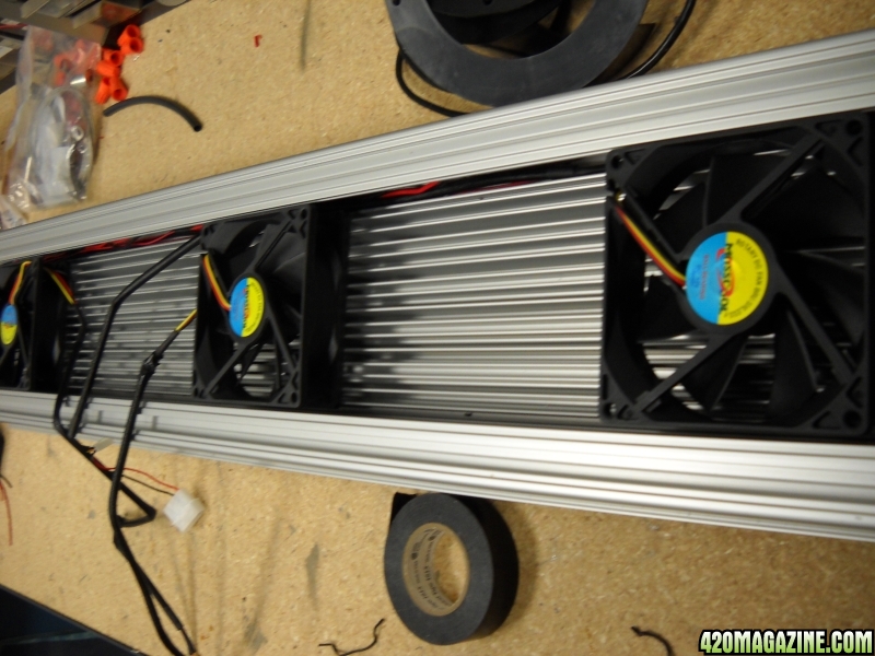
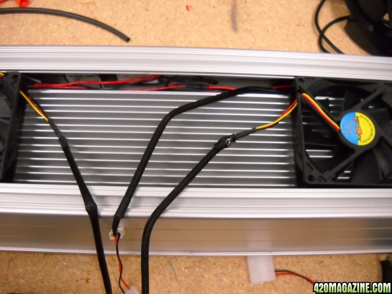
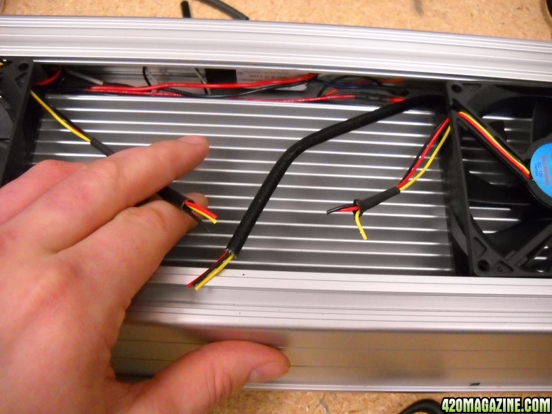
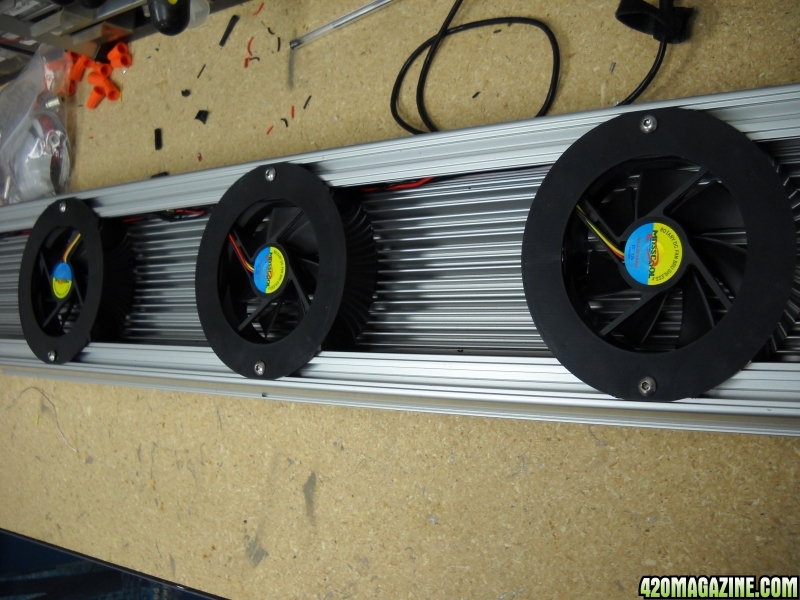
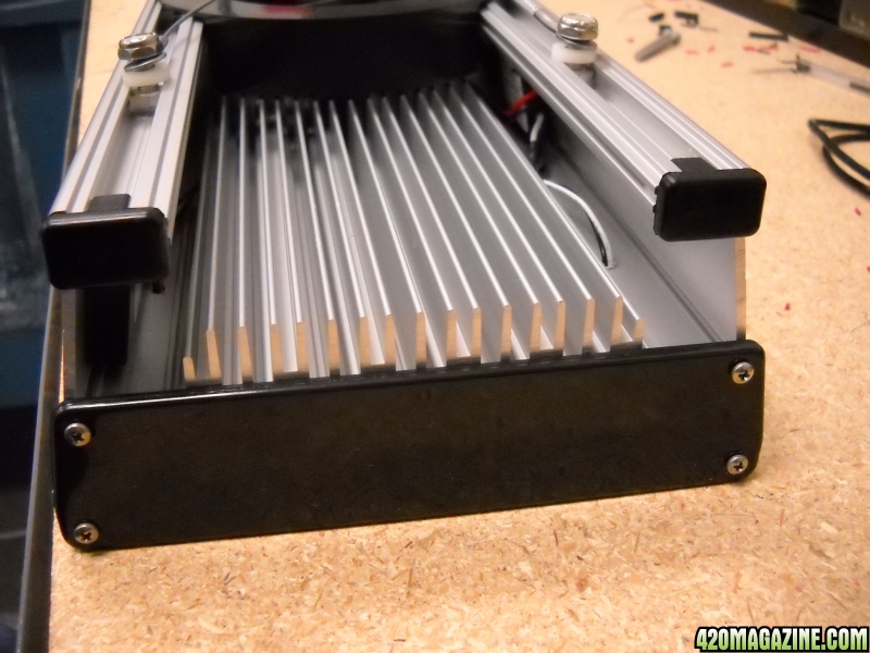
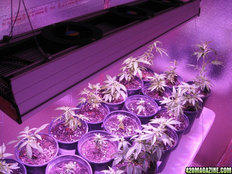
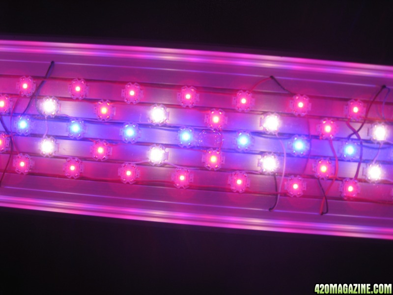
• 300w custom LED
*Carbon scrubber & fan will be added before the flip*
 
Let’s start with the ladies. Some are already much taller than others and that might play into shading so I’m going to set the taller ones on the edges.

69460z.jpg

nn8lz7.jpg

o05swo.jpg


Here is the LED fixture. I forgot to put on some shades when I turned it on – super bright. It fluctuates between 309w and 311w

155jhok.jpg

16iib04.jpg
 
Building this was a true learning experience. Thankfully ledsupply had some great techs that helped me through the build. I took some photos and made instructions.

I went with a 3' makersled heatsink

Here are the parts & materials I used to make the fixture.
  • (1) MakersLED Heatsink Kit w/ Hanger – for $49.92/Ft
  • (36) Deep-Red Luxeon Rebel LEDs – for $6.94ea
  • (9) Red Luxeon Rebel LEDs – for $5.28ea
  • (9) Red-Orange Luxeon Rebel LEDs – for $5.28ea
  • (18) Royal-Blue Luxeon Rebel LEDs – for $4.60ea
  • (18) Warm-White Cree XM-L LEDs – for $7.94ea
  • (6) 700mA FlexBlock LUXdrive Drivers – for $17.99ea
  • (3) 1000mA BuckBlock LUXdrive Drivers – for $17.99ea
  • (3) 1400mA BuckBlock LUXdrive Drivers – for $17.99ea
  • (3) 24VDC 4.5AMP Power-Supplies – for $34.99ea
  • (1) 12VDC 1.0AMP Power-Supply – for $9.99ea
  • (3) Arctic Silver Thermal Epoxy – for $15.99ea
  • (75') Red 24AWG Stranded Wire – for $0.25/ft
  • (50') Black 24 AWG Stranded Wire – for $0.25/ft
  • (30') White 24 AWG Stranded Wire – for $0.25/ft
  • (20') Blue 24 AWG Stranded Wire – for $0.25/ft
  • (30') Orange 24 AWG Stranded Wire – for $0.25/ft
  • (12') 2 Conductor Shield Wire
  • Heat-Shrinking Material


Tools, Equipment and resources needed to get the job done
  • Solder Iron & Solder
  • Wire Strippers
  • Tweezers
  • Hand-held Drill
  • Latex Gloves
  • Philips Screw Driver
  • 10mm Wrench
  • Wiring Schematic
  • FlexBlock Data Sheet (Boost-Only Mode Wiring Diagram)
  • Red, Black & Blue Sharpie Markers
 
Here are some general step by step of what I did to build it. I might have missed a step but pretty sure I covered everything.

• Organize Materials
003_zps9f98a464.jpg
– Double-check all part#'s & quantities
• Add Solder to ALL solder pads on EVERY LED
• DOT LED location on heatsink w/ appropriate color sharpie markers
004_zps086eb6b4.jpg

1. See LED Schematic
2. Measure, Mark & Divide the heatsink into equal 3rds (DOT 1-foot at a time)
3. “Approximately” (start 1” in from end and space DOTs 2-inches apart)
 
• Apply Epoxy & Place LEDs

1. Set-up correct pattern of LEDs before applying epoxy
2. Mix appropriate amount of Epoxy (5-minute cure time) – Shoot for 8-LEDs every 5-minutes
3. Hold LED in left hand between index finger and thumb
005_zps60e9322c.jpg

4. Apply Epoxy down center
007_zpsf2f2a926.jpg
,
Rotate 25-degrees in fingers and Epoxy down Center
006_zps4318fd91.jpg
, Rotate opposite direction 50-degrees and Epoxy down center
5. Place LED over appropriate DOT on heatsink
6. PUSH down with Right hand
008_zps6c01b390.jpg
 
• Complete EACH circuit with Positive & Negative Wires
1. For the Positive Wire use the appropriate COLOR WIRE for the color of the LED (Red Wire for Deep-Red Circuit, Orange Wire for Red & Red-Orange Circuit, White Wire for Warm-White Circuit and Blue Wire for Royal-Blue Circuit)
2. Use Black for ALL Negative connections
3. Cut ALL these wires long enough to run to the side (where drill holes will evenutally be) and be run up through the heatsink with enough wire to work with
014_zps4be8027d.jpg

• Drill Holes for Wire (See above pic for reference)
1. There will be six holes per side
2. Run Positive & Negative wires neatly and in the straightest path to the side of heat-sink and determine where all the holes need to be drilled. Mark & Drill.
 
• Run Wires through Drill-Holes & Tape to the side of the heat-sink
• Solder Positive & Negative wires to Positive & Negative Output Wires of APPROPRIATE LED Driver:
1. (700mA FlexBock for Deep-Red in Boost-Only Mode)(700mA FlexBock for Red & Red-Orange)(1000mA BuckBlock for Royal-Blue)(1400mA BuckBlock for Warm-White)
2. Connections are made by stripping back both wires, adding heat-shrink tubing to wires
018_zps1246ba49.jpg
, Solder wires together and cover connection with heat-shrink
3. Cut away excess wire before stripping to save space
017_zpsd39fd540.jpg

4. Cut away dimming wires and tape over end of wire
016_zps97bc8d25.jpg

5. Special Connection must be make for Deep-Red Circuit (see FlexBock Datasheet for Boost-Only mode connection diagram)
6.
015_zpsba95287a.jpg
019_zpsb1e7a2ee.jpg
 
Locate ALL Red & Black INPUT wires on the LED Drivers and TAPE them to the side of the heat-sink
019_zpsb1e7a2ee.jpg

One-Foot at a time: Solder RED wire to RED Wire on LED Drivers, long enough to stretch the length of the heat-sink
020_zps5a5c42af.jpg

One-Foot at a time: Solder Black wire to Black Wire on LED Drivers, long enough to stretch the length of the heat-sink
020_zps5a5c42af.jpg

Connect ALL Red wires to each other (see pic above)
Connect ALL Black wires to each other
021_zps20b965a0.jpg
 
• Connect ALL Red wires to the Red wire on the 2 Conductor cable
020_zps5a5c42af.jpg
026_zpsa35709b5.jpg

• Connect ALL Black wires to the Black wire on the 2 Conductor Cable
021_zps20b965a0.jpg
020_zps5a5c42af.jpg
026_zpsa35709b5.jpg

• Heat-Shrink Red & Black Connections to the 2 Conductor Cable
023_zps817fbed7.jpg
022_zps0d78a592.jpg

• Connector 2 Conductor Red & Black wires to appropriate Power-Supply Output
024_zps56070b78.jpg

• Connect Power-Supply CORD to Power-Supply, Wire with writing goes to “L” on Power-Supply (see pic above)
 
• Cut excess wire
• Don't use yellow
• Attach ALL REDs, Attach ALL Blacks
• Strip off barrel plug on 12VDC 1.0AMP fan power-supply and expose wires, wire with writing is Positive
• Attach and heat-shrink RED wires to positive wire on power-supply
• Attach and heat-shrink BLACK wires to Negative wire on power-supply
• Hide excess cords and wires along edge of heat-sink and run plug out with the other wires
• Attach rubber end plugs (use soap and water)
• Attach end caps
• Attach Hangers

031_zps046fc601.jpg

032_zps0760bcf4.jpg

033_zps27c1ad33.jpg
 
Back
Top Bottom