

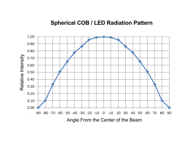
The most important thing to understand is that LEDs and COBs are NOT point light sources. They do NOT radiate light equally in all directions in a spherical pattern. They put out a beam of light much like a directional radar antenna, or a vertical HID with a reflector. This beam is stronger in the center, and the power drops off as you rotate away from the center. This graph is published by a COB manufacturer for their radiation pattern. You should be able to find similar data from other manufacturers.
 This graph shows the intensity of the LED or COB relative to the highest value at the center of the beam, as you rotate away from the center. It’s important to note that this is for devices without built-in lenses or reflectors. All further discussion is based on this chart. The best way for most people to visualize this is to reorganize the graph like this:
 This shows the same data as we move around a semicircle centered on the emitter. It’s still not very useful to us as we need the data for where the light hits the flat plane of our ideal canopies. To do this we apply the inverse square law to the values from the graph above, and get the following:
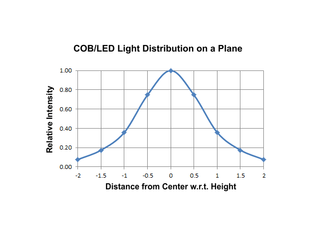 This graph shows the relative power or intensity of the beam as it hits the canopy. The COB or LED is centered one unit above a canopy or plane four units in length. It doesn’t matter what the units are, inches, feet, meters, choose what’s most natural to you. I’ve done the calculations at half unit intervals along the canopy.
It's been several hours relearning material I haven't used for years, and running the calculations. It's important to remember these devices have no built-in lenses or reflectors to concentrate the light. As you can see from the last graph, you can choose light that varies greatly or wasting a lot of the light. The ways grow light manufacturers expand the usable area include lenses, reflectors, and using multiple emitters in larger fixtures. In addition, we as growers use tents or rooms with reflective surfaces to recover some or most of the light that doesn't directly hit the canopy. I'll look into these in another post, as I have the time.
It's been several hours relearning material I haven't used for years, and running the calculations. It's important to remember these devices have no built-in lenses or reflectors to concentrate the light. As you can see from the last graph, you can choose light that varies greatly or wasting a lot of the light. The ways grow light manufacturers expand the usable area include lenses, reflectors, and using multiple emitters in larger fixtures. In addition, we as growers use tents or rooms with reflective surfaces to recover some or most of the light that doesn't directly hit the canopy. I'll look into these in another post, as I have the time.
")

