Buckshot317
Plant of the Month: Mar 2018
Get a 2.5 amp fuse, that's just hair higher than your 2.1 max to cobs. Voltage is meaningless on fuses, their sized by current. I'll look around the net, see if I can find something. Maybe fan might have different idea.
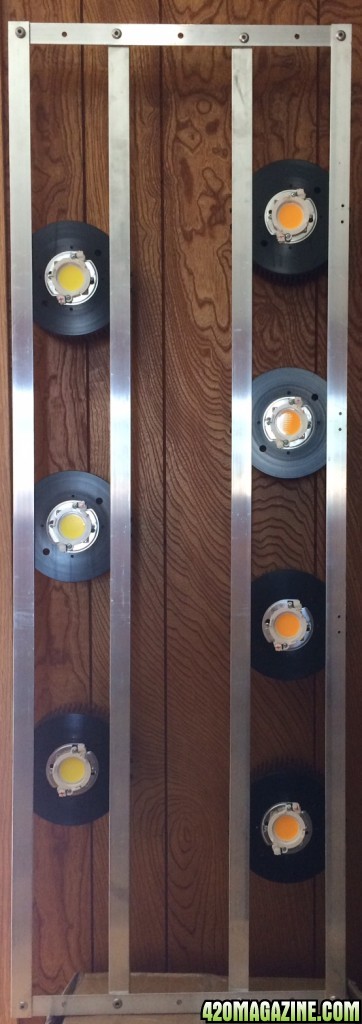
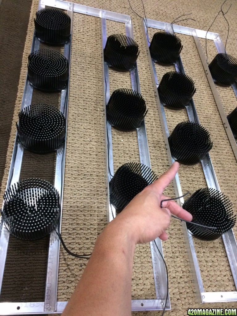
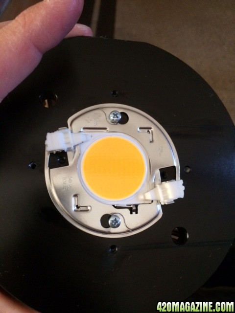


 when I wired my cobs I had two in backwards polarity they did not burst, pop or burn when I applied power to the driver are they going to be ok?