300W LED replacement help

Triffid

420 Member
I have a couple of Viparspectra 300w lights with burnt out led's, have the replacement LED's, and am stuck on getting the burnt ones off.

I have desoldered the connections off, but the led itself will not come off. It's a little damaged now (well completely destroyed would be a better desciption), and just the internal heatsink is still attached..

Can anyone tell me what I have done wrong in trying to removing this?

20200306_102900.jpg
 
It looks like those are soldered on also? This isn't really clear but might give you another perspective. CHeers, gl! :yahoo:

 
Thanks for that Pbass =)

That video, and all the others I have found like it for replacing led's, indicate you can unsolder it and easily remove, with a nudge, push, or a little leverage.

I have unsoldered, but it refuses to come off.

I can melt the plastic frame off, as you can see in the picture, there is a aluminium heatsink inside the plastic mounting, that I just have not been able to shift.

I have tried using a screwdriver, the blade of a knife, even a razorblade but I cannot get under the edge at all.

Can I use a hammer and chisel on it, or am I missing some really simple step in getting them off?
 
Any way you can dig into that thing further and see what the back of that circuit board looks like? Maybe VP solders them on the back.
 
Viparspectra v300

with the burnt LED in the rest of the lights flicker "just" on
with a bridge soldered from + to - the rest of the lights flicker "just" on
without the LED or a bridge, none of the lights turn on at all

I was hoping by replacing the LED I would be able to get it back up to full power

The back of the board definitely has no solder connections,
4 holes in the front of the board per heatsink, and another 4 for the reflector mounts

20191108_145933.jpg


From Viparspectra support, they have sent replacement LED's for warranty, with the very precise instructions of
1. Unweld connections for damaged LED and remove from board.
2. Weld connections for new undamaged LED.

I have tried to get clarification on "how" to unweld (also tried to get clarification that unweld meant unsolder....),
but this seems to be their supports only response about how to replace damaged LED.
 
It apperes to me it's glued down with the thermal interface crap that's used to transfer the heat to the heat sink..

Right, method of removal if this is the case?

1. Would a heat gun work (Don't have one to test myself sorry)
2. Isopropyl?
3. Acetone?
4. Hammer and chisel

thanks for recommendations =)
 
That must be a plastic heat sink, going by the price it's sold for.. Since it is as good as worthless the way it is, I would try a very sharp 1/4 inch wood chisel, at the lowest angle possible.. Gently tapping at the interface, from alternating sides.. From what I can tell by the pics of the led, it appears the base is plastic.. Could be the heat transfer stuff has welded the base of the led to the heatsink.. This is all supposition on my part based only on the pics.. Be brave, but gentle, if go that route..
 
Triffid, I'm running against the same problem as you did - dead led and trying to get the thing out

would be really interested if you managed to get it out in the end - and how.

Thanks for sharing
 
Close_up.jpg


I tried a hairdryer with no luck, then a heat gun, still wouldn't come free.

Finally, with a considerable amount of effort, got a razorblade under the edge enough that I could get a chisel tip under and off it came. Not sure what was used, adhesive wise, but the damage getting it out with a chisel made it look like it was welded. Got the area cleaned up as nicely as I could, soldered a new LED in and away we went.

For a couple of days till another one blew out..... have now confirmed all of them seem to be welded on, so am giving up on redoing the board.

Upside, I now have 3 Drivers that need re-purposing,
LT-2F-B51140W-F (LED Grow Light Power Supply with UL certificate)

any ideas about what to do with them?
 
It's a bit of an odd duck power supply.
Constant current with voltage adjustable from 140v-180v and 140w max output.

You could run seven 24v quantum strips in series to give you the ability to handle the voltage but you would only be driving each strip with 20 watts a piece at max power. That being said 140w of quantum strip power is pretty good stuff.
 
I was in the exact same situation. Led light with a burned up panel. I mounted six Samsung SunBoards to the bottom of the frame and wired everything up. Works great.

IMG_20200504_175647713_HDR.jpg
IMG_20200504_175641304.jpg
 
You know when you have one of those pivotal moment's when your thought structure shifts...

You could run seven 24v quantum strips in series to give you the ability to handle the voltage but you would only be driving each strip with 20 watts a piece at max power. That being said 140w of quantum strip power is pretty good stuff.

This was it! I had not even considered strips, for whatever reason I was blinkered, until I read that, saw the pic, and did a bit of research. I had been designing a COB build so that I was independent in repairs and replacements, and just glossed over all the strips, fixated on the "less components". Thankyou FatBeaverBuds!

I had to relearn some maths to get my head around what could be done with the drivers with this idea, but cost wise for DIY with lumen/watt, strips seem to be amazing. Add a desire for less head height and less heat production, and I don't know what the hell I was thinking of before!

Am I right in thinking a constant current driver that supplies ~665ma (is that right?) and 140v to 180v could power
3x 48v strips = 144v
4x 35v strips = 175v
5x 25v strips = 175v
(as long as the voltage at that current is within 140-180?)
 
Glad I could help :passitleft:

I think the three 48v strips in series is your best option. That would be 47 ish watts per strip. Really depends on the quantum strips you use.

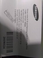
I got mine off of fleabay. Three 16" strips for $60. Legit (I think) Samsung strips with LM301b diodes.

IMG_20200513_074816354.jpg
 
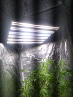
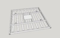
Got it all up and running now, fantastic way of re-purposing the drivers. Have my drivers mounted on the plate in the plan, no fans so a nice little silent passive build, puts out ~850 PAR at 15cm across my 2x2 space.
 

Attachments

  • Tslot.Frame.jpg
    Tslot.Frame.jpg
    287.1 KB · Views: 151
Close_up.jpg


I tried a hairdryer with no luck, then a heat gun, still wouldn't come free.

Finally, with a considerable amount of effort, got a razorblade under the edge enough that I could get a chisel tip under and off it came. Not sure what was used, adhesive wise, but the damage getting it out with a chisel made it look like it was welded. Got the area cleaned up as nicely as I could, soldered a new LED in and away we went.

For a couple of days till another one blew out..... have now confirmed all of them seem to be welded on, so am giving up on redoing the board.

Upside, I now have 3 Drivers that need re-purposing,
LT-2F-B51140W-F (LED Grow Light Power Supply with UL certificate)

any ideas about what to do with them?
I got two VS v300(135w) reflector series...Angle of led light spread is 90° because reflecting plate .Anybody try to remove that reflective cover under leds? Then light spread is increased to 120°
I always scare to mess with lights because I'm always on budget or short on money...Can I gain something on 120° or lights power goes down with no cover?
I got one new led driver from optonica 350w.
Can I change drivers and gain more power like this?I know that that will short lifetime of led diods.
Final question is can I with new driver boost my v300 130w to 200w?
If questions break any rule feel free admin to delete the post.
 
Back
Top Bottom