Mars-Hydro TSL-2000: Unboxing & Installation

About 6" (15cm) below the canopy the temperature is the same as the incoming air. The drivers are still on the light. I'm making an extension cable to move the drivers out of the tent for ease of adjustment.
 
The growth is amazing
 

Attachments

  • BF6B0FEC-7900-447D-B9E1-5ECC4213E0AA.jpeg
    BF6B0FEC-7900-447D-B9E1-5ECC4213E0AA.jpeg
    999.1 KB · Views: 169
  • 25CE9F0D-68AE-489C-B810-638A9C01893B.jpeg
    25CE9F0D-68AE-489C-B810-638A9C01893B.jpeg
    1 MB · Views: 147
  • 26DF1466-7805-4B4F-9FA3-42A95913693E.jpeg
    26DF1466-7805-4B4F-9FA3-42A95913693E.jpeg
    1 MB · Views: 135
  • 27826278-EAD2-4795-9574-18285BC71D95.jpeg
    27826278-EAD2-4795-9574-18285BC71D95.jpeg
    972.7 KB · Views: 127
About 6" (15cm) below the canopy the temperature is the same as the incoming air. The drivers are still on the light. I'm making an extension cable to move the drivers out of the tent for ease of adjustment.

How do you make the extension cable?
I would like to run the drivers outside of the tent if possible because any extra heat has always been an issue with where I am.
 
How do you make the extension cable?
I would like to run the drivers outside of the tent if possible because any extra heat has always been an issue with where I am.
I'm working on it, and should have the instructions ready to post tomorrow.

Here's a preview of the finished cable...
full

Completed Extension Cable
 
My tsw2000 came with 2 meter long extension cords but ive decided to leave the driver above the light rather than out tent to provide a tad more heat, in the summer i will most likely mount it outside of the tent. The light and driver runs a little warm and as a precaution i tied the wires so they dont touch the top side of the light or the driver, even if they were touching i think the cords are thick enough to withstand the heat but i just did it out of my own comfort. Plants are really liking the light too!
 

Attachments

  • 20200119_105600.jpg
    20200119_105600.jpg
    552.7 KB · Views: 147
  • 20200119_105554.jpg
    20200119_105554.jpg
    505.5 KB · Views: 154
My tsw2000 came with 2 meter long extension cords but ive decided to leave the driver above the light rather than out tent to provide a tad more heat, in the summer i will most likely mount it outside of the tent. The light and driver runs a little warm and as a precaution i tied the wires so they dont touch the top side of the light or the driver, even if they were touching i think the cords are thick enough to withstand the heat but i just did it out of my own comfort. Plants are really liking the light too!
Are they extensions, or just extra long leads from the drivers?
 
Its just the originals that came with the lights. Im assuming they extended the cords in the recent shipments to allow for ease to mount outside of tent, as i heard this may be an issue but the extra long cords would make the switch very easy without additional mods.
 
I think so....how long were the cords that came with your light?

It depends on the model. Both the TSL-2000, and TSW-2000 have cables that are just a little longer than needed to reach the jack on the LED panels.
 
Ya okay so the cords must be longer on the newer orders. I like your diy extension, glad i didnt have to jig up something like that!
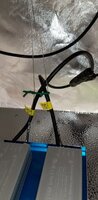
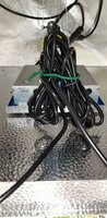
There are 1.5m (59") DC5525 extension cables available through e-Bay for about $2.00 each. There are two reasons I didn't buy them. They don't specify the wire type (size, stranded or solid core), and the wire used is copper coated aluminum. Aluminum wire was used in North American homes during the '60s and '70s. It caused a lot of house fires and has since been banned.
 
Making Your Own Driver Extension Cables

Mars Hydro has extended the length of the cables from the drivers to the LED Panels to two meters for the lights currently being produced. Those of us with lights manufactured prior to the change will need to find or make our own. Two meters may not be long enough for some with the more recently manufactured lights.

Let's first take a look at what's needed for those of us with the older lights. We need enough cable to reach the center of the light, for the TSL-2000, this is about 65cm. Then we need 100cm in the tent to raise and lower the light. Next we'll need enough cable to reach the drivers, where ever we have chosen to mount them. If we have the drivers with the 2 meter cables, we'd barely have enough to reach the front of 2' (60cm) deep tent using the straightest path possible.

I checked on e-Bay, for appropriate extension cables. I found 150cm extension cables described as 'DC5525 Power Cable Male to Female Plug Extension Cord Adapter.' I don't trust these cables. They are made from copper coated aluminum wire. Aluminum wire was used in the past for homes in North America. It resulted in house fires. That's not what I want for my tents. Another problem is that they don't specify the gauge of the wire, or if it's stranded or solid core. We want 18ga wire to handle the current, and flexible stranded wire rather than solid core wire. My advice is don't buy them.

Having established the need, let's look at one implementation:

full

Finished Extensions in Action


How to Make Your Own Extensions:

Warning:
Do mot attempt this unless you have the proper tools, and some experience soldering. Your safety is your responsibility. If you have any concerns about these procedures, DO NOT TRY THIS!

First we need to make a design decision. Are we going to use one cable for both drivers that splits at the ends to go to the LED panels and drivers, or a separate cable for each driver/LED panel? A single cable is easier to manage for installation, and moving the light in the tent. Separate cables are easier to make, requiring eight less solder connections. They can be grouped using cable ties to get the benefits of a single cable. I chose a single cable.

Note: Click on any image below to view it full size. Full instructions are below the images.

full

1. Cables and Connectors

full

3. Wires at 'Y' Soldered

full

5. Cord Covered With Heat Shrink

full

7. Male Connector Ready to Solder

full

9. Completed Extension Cable
_______________________________________________________________​

full

2. Wires at 'Y' Ready to Solder

full

4. Splice Covered With Cord

full

6. 'Y' Covered With Heat Shrink

full

8. Male Connector Soldered

full

10. Cable Installed on the Light
_______________________________________________________________​

1. Cables and Connectors
The first step is to order the cables and connectors. I ordered cables with 18ga stranded copper wire for the flexibility and current carrying capacity I wanted. I used 3 meters of four core cable and about 2 meters of two core cable. If you plan on using a separate cable for each driver / LED panel order the length you need and add 75cm to that length for the ends to reach the LED panels from the center of the light. I used 65cm at my light, and 20cm at the driver end. You will also need two male and two female DC 5525 connectors. They are cheap, so I ordered a few spares, just in case I messed one up. These parts can be ordered through e-Bay.

Other consumed items I consider shop supplies. I used heat shrink in 3mm, 7mm, 10mm and 13mm sizes. The 7mm I used in both black and green. The green was used to mark the cable ends for one of the driver / LED panel runs. Also needed are solder and rosin flux. You may need appropriately sized cable clamps, and cable ties as well.

The tools you'll need are a measuring tape, soldering iron, wire cutters, wire strippers, small sharp scissors, a sharp knife, and an Ohm or multi-meter.

2. Wires at 'Y' Ready to Solder
These next few steps are for splitting the four core cable into two, two core cables. Don't skip ahead to the end connectors quite yet if you plan on using separate cables for each driver/LED panel. I'll cover removing the sheath from the cables here.

The first thing you need to do is remove part of the cable sheath. Care must be taken not to damage the insulation on the individual wires. I score the sheath with a sharp knife at the point I want the individual wires exposed, taking care not to cut through the sheath. I then insert the pointy blade of the scissors into the end of the cable and cut down its length until I reach the score, once again taking care not to damage the insulation on the individual wires. The sheath can then be pulled off along the score. I do it this way both to protect the wires, and as I often can't pull the sheath off of the cable. OK, those making individual cables for each driver / LED panel can skip ahead to step seven now.

I used three meters of four core cable, and two lengths each for the 70cm and 20cm connecting ends of two core cable.

I removed about 8 cm or three and a quarter inches of the sheath for both the four and two core cables. At this point note which wire pair in the the four core cable you'll use for each driver/LED panel. I was lucky enough that my four core cable have the same color blue and brown wires as the two core cable. I used these for one pair, and the remaining black and yellow/green wires as my second pair like this:
Four CoreTwo CoreUsage
BlueBlueDriver/LED panel 1
BrownBrownDriver/LED panel 1
BlackBlueDriver/LED panel 2
Yellow/GreenBrownDriver/LED panel 2


I like to stagger the wire joints when I join two cables together. This produces a smoother end product, and reduces the chances of a short circuit. I cut off 2.5cm or an inch from the blue and black wires from the four core, and the brown wires from the two core cables. I stripped 20mm or 3/4" of insulation from each of the wires at the joints. The strands were twisted back together after this. I then slipped heat shrink over the longer wires. DO NOT FORGET THIS! I have in some of my previous projects, and had to take the joints apart to correct this mistake.

3. Wires at 'Y' Soldered
The wires were mechanically joined using a 'Linesman's Splice.' (Google this if you don't know how.) Rosin was applied to the joint, which was then soldered. Only a little solder is needed. A 'Big Frigg'in Blob of Solder' is wasteful, and can lead to problems in the future. Do one joint first, then make the splice for your second joint, so the wire is just a little bit shorter. Give the cables a light pull, and the wires will be the same length. Solder your second joint. The heat shrink was slid over the joints, ensuring that it extended over the insulation at both ends, and heated to complete them.

4. Splice Covered With Cord
We now have a cable that is missing part of its sheath. This should be replaced. Putting a piece of heat shrink over it will leave the area depressed. I chose to use cord to fill it with a whipping. (Google this if you don't know how) .

5. Cord Covered With Heat Shrink
With the whipping complete, I covered it all with heat shrink, ensuring the heat shrink was long enough to cover the remaining sheath of the two core cable by 2.5 cm or an inch. If you haven't done so, complete steps two through five for the other cable of the pair.

6. 'Y' Covered With Heat Shrink
Next, I cleaned up the transition from one cable to two cables. To do this I put a short whipping around the four core cable right next to the two, two core cables. I then used a 50mm or two inch piece of heat shrink to cover the transition, ensuring that it covered the two connection cables by at least 15mm or five eighths of an inch. I heated it to shrink it down and hold everything together.

Now do the connection cables at the other end the same way. Ensure that you know which wires you are connecting.

7. Male Connector Ready to Solder
This is where you should rejoin us if you are using separate cables for each driver/LED panel.

Putting the connectors on the cable ends is the same for both the male and female connectors. There is often confusion as to which is male or female. I was taught to go by the center terminals. If it's inserted into its mate then it is male, so I'll stick with that. The ones on e-Bay are labeled the opposite way at the time I'm writing this. The male connectors are for the driver ends of the cables, and the female ends plug into the LED panels. I ran into two problems with the connectors. The shell was too small to slip over the two conductor cables, and the wires were too large to be tinned before insertion into the appropriate holes in the connectors.

Remove 12mm of the cable sheath. Cut the wire for the outer terminal back 3mm or 1/8".

I cut the end that slips over the cable off of the shell, trimming it so I could slip it over the cable. I slipped a short piece of green heat shrink over one of the long two core cable ends. At the other end of our assembly, I used my multi-meter to find its match and slipped a short piece of green heat shrink over it. Using the colored heat shrink lets us determine which driver is for each of the LED panels when it's in use. Slip the shell over the cable next, making certain it is oriented correctly. Make the mechanical connection for the center terminal first, apply your rosin, and solder it. Repeat for the outer terminal.

8. Male Connector Soldered
Now that we have the two wires soldered to the connector, finish off the other three connectors. Lay the wires through the tabs on the outer connector, and bend the tabs over to secure them. The sheath for the cable should be no more than 1/2mm from the tabs. Screw the shell over the connector, and verify that the sheath extends into the connector. Slide the green heat shrink marker over the sheath against the connector shell. Apply heat to hold it in place. Cut four pieces of heat shrink that will slip over the connector so that they are long enough to cover the entire shell, and about 20mm or 3/4" of the cable. Apply heat to shrink it and mold it to the connector and cable. Repeat for the remaining connectors.

9. Completed Extension Cable
Once we reach this stage the cable must undergo preliminary testing for open and short circuits. Start with checking for shorts. This can be done at one end of the cable assembly. Check between the center and outer terminals of each connector. Then, if you've used four core cable, check between the center terminal of one of the connectors, and the outer terminal of the other connector. Check between the same inner, and the inner terminal of the other connector. Repeat the measurements for the outer terminal of the first connector, and both terminals of the second connector. All of these measurements should indicate that there are no connections.

Next we ensure that we have an electrical path between the male and female ends. Check for conductivity, or zero ohms between the center connectors of each cable pair. Do the same for the outer connectors.

If you made it to this point, then congratulations, you are ready to install the cable.

10. Cable Installed on the Light
On the driver mounting plate of the light, remove the nuts in the center where you will mount the cable clamps. You did save them, didn't you? Plug in the long two core cables to the LED panels of the light, ensuring that they run through the center of your light hangers if they are installed. I installed the cable clamps in opposite directions, with the cable part oriented to the center of the light, and used the nuts we removed to hold them in place.

Mount your light in the tent, then run your cable out of the tent to your drivers. I suggest using heat shrink to hold the connectors together for each cable to driver connection. This will prevent them from being accidentally disconnected. The heat shrink is easily removed by cutting through it at the center where we have some metal to prevent connector damage. Pull the connectors apart, score the length of the of the heat shrink left behind, and pull the heat shrink apart with pliers.

Now turn on the power to the drivers. The LED panels will light up if everything was done correctly. Congratulations! you have just completed your extension cable.
 
Thank you very much for sharing, :thanks:very detailed explanation, :adore:if anyone wants to extend the power cord, be sure to check out old salt's share
Are you guys planning on selling the extended wires that you now sell with the newer version light?
Would be very helpful for people with the lights with the short ones and have no idea on how to solder.
Cheers
 
Day 22 from flip.

I am so impressed with this light. Coupled with Mega Crop I am loving life!!!
 

Attachments

  • F2E72F12-185B-4233-89F9-EA02FBC1A870.jpeg
    F2E72F12-185B-4233-89F9-EA02FBC1A870.jpeg
    1,015.6 KB · Views: 130
  • 717E1567-9EF4-4DFE-AA89-63E7E1C0BFDC.jpeg
    717E1567-9EF4-4DFE-AA89-63E7E1C0BFDC.jpeg
    1.2 MB · Views: 130
  • 4B170DF8-DD7E-457E-B737-123F4AC55922.jpeg
    4B170DF8-DD7E-457E-B737-123F4AC55922.jpeg
    1.1 MB · Views: 134
  • 3F24FDE9-6AA2-4CB3-A07C-A73F32BE464D.jpeg
    3F24FDE9-6AA2-4CB3-A07C-A73F32BE464D.jpeg
    1.1 MB · Views: 143
  • 46EDBB85-FE11-437E-9600-1F8A48C2255E.jpeg
    46EDBB85-FE11-437E-9600-1F8A48C2255E.jpeg
    1 MB · Views: 119
  • FD2A8A2B-FBA4-4200-AE75-3F002DDA7B6F.jpeg
    FD2A8A2B-FBA4-4200-AE75-3F002DDA7B6F.jpeg
    1 MB · Views: 131
  • B74DFF97-EAD9-4B8A-B3EA-4650003EC3F8.jpeg
    B74DFF97-EAD9-4B8A-B3EA-4650003EC3F8.jpeg
    1 MB · Views: 120
  • 56F1DDCE-275F-41DA-B333-30FA27FEB7A3.jpeg
    56F1DDCE-275F-41DA-B333-30FA27FEB7A3.jpeg
    953.5 KB · Views: 120
  • 686F0CD7-B52E-42CA-BF51-ECFA2BD7408E.jpeg
    686F0CD7-B52E-42CA-BF51-ECFA2BD7408E.jpeg
    1,014.3 KB · Views: 121
  • 712CF7A4-72CA-4A32-BE47-BE76E7D60A96.jpeg
    712CF7A4-72CA-4A32-BE47-BE76E7D60A96.jpeg
    951.3 KB · Views: 142
Are you guys planning on selling the extended wires that you now sell with the newer version light?
Would be very helpful for people with the lights with the short ones and have no idea on how to solder.
Cheers
We have been selling extended wires, but we can only ship from China to other countries. International shipping is not cheap. And customers still need to solder the extension wires by themselves. Therefore, we recommend that customers buy from local hardware stores or eBay, which can save your costs.
 
Hi. sorry to be a pain and jump in with a request.
Could someone please upload the manuals in pictures?
I have the TSL 2, new version, and can not find my manual lol. Old version TSL manual would be ok too.


if your tent is hot your can ad a blower and filter too empty tent 2 times a minute..

 
Back
Top Bottom