

Navigation
Install the app
How to install the app on iOS
How To Use Progressive Web App aka PWA On 420 Magazine Forum
Note: This feature may not be available in some browsers.
More options
You are using an out of date browser. It may not display this or other websites correctly.
You should upgrade or use an alternative browser.
You should upgrade or use an alternative browser.
Arduino based room controller
- Thread starter OG13
- Start date
- Thread starter
- #185
OG13
New Member
What voltage does an digitalWrite put out to the pin? 5v?
Yes 5v
Make sure to declare that pin an OUTPUT.
- Thread starter
- #186
OG13
New Member
Lesson 6 Standalone RTC Timer functions, control your lights
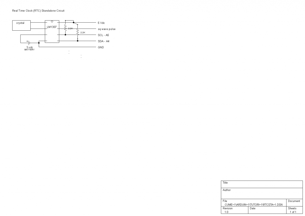
In this lesson, I will show a standalone RTC that I made. It only costs $4 in parts, which can save some money over a datalogger shield if you don't want to log. I got the parts from bbkelectronics, but any decent supplier will have the same parts. You need the DS1307 chip, a DIP socket is nice, 2 resistors around 2.2kohms, a small 3 volt lithium battery and holder, and some protoboard (stripboard works nicely). I used some pins to make it easy to use in a breadboard. Here's the schematic.
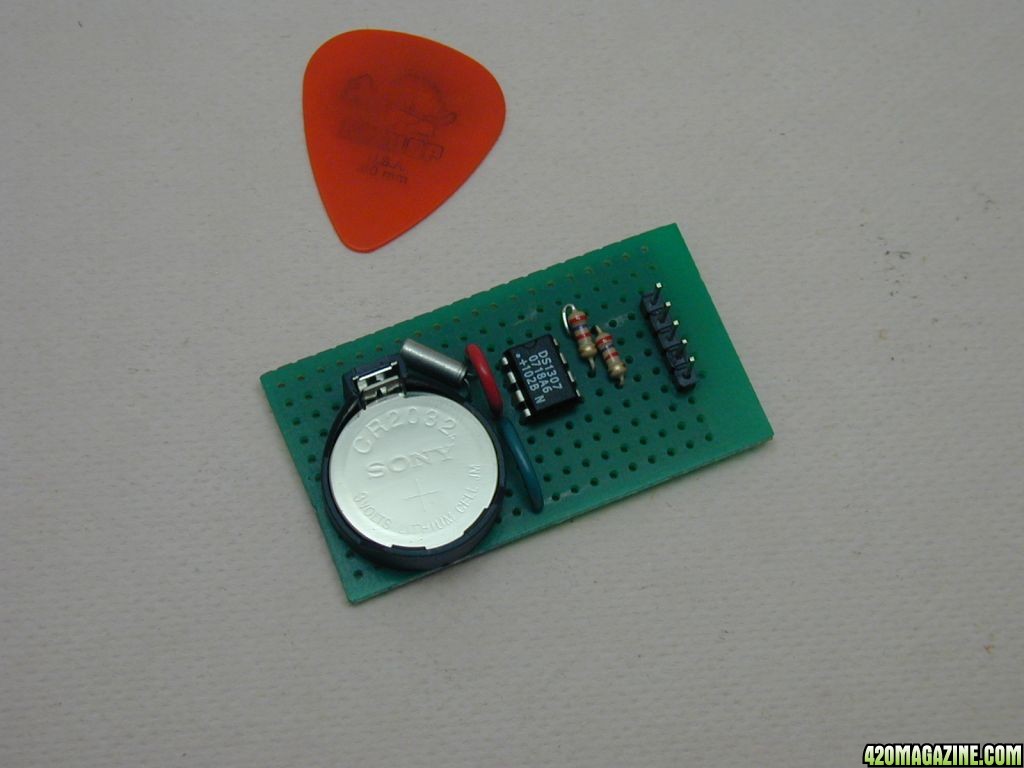
Here's a pic of the completed RTC board.
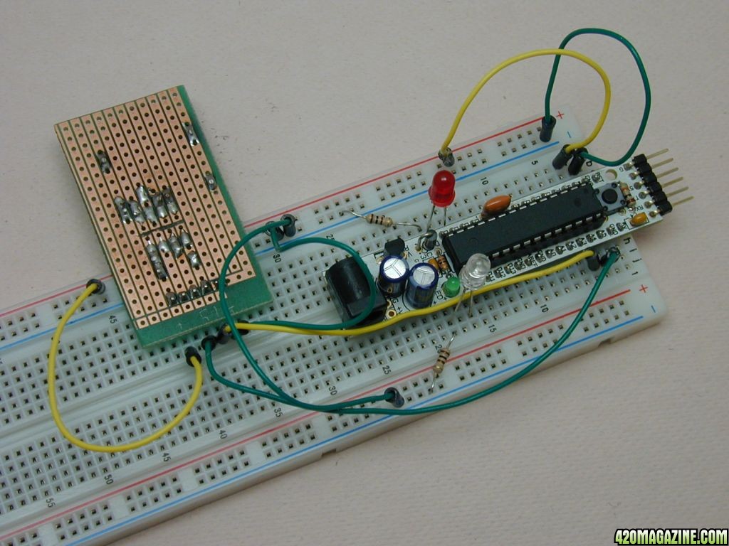
You will use the same libraries as you did with the datalogger, since it is the same clock. You will need to hook it up to the arduino—SCL to A5, SDA to A4, power and ground. Set the time like you did for lesson 5. You can see that I'm now using a Really Bare Bones Board from Modern Device. It is nice and small and won't be hooked to the PC in the coming project. It makes working on a breadboard really easy. It does require the programming cable/FTDI/Buddy, but is cheaper if you have more than one arduino.
For the light timer, I added a couple of LEDs and resistors to pins D7 and D9 just to demonstrate. You would use whatever relay/powertail you desire to drive your load. Play with the values for on an off time and make sure they work like advertised. Here is the code for the timer..... GitHub - OG13/Lesson6: Standalone RTC controlling 2 light cycles
and a pic of the setup.....
Here's the schematic.....
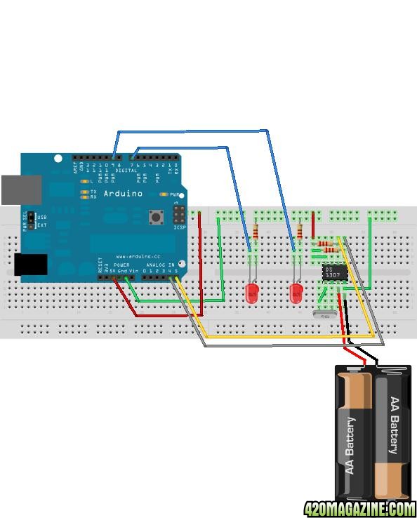
The only limitation of this design is that the lights will remain “off” if you power up the arduino during the “on” time period. They will start operating normally the next “on” period. I may incorporate a manual switch override into the next design. This is just proof of concept.
In this lesson, I will show a standalone RTC that I made. It only costs $4 in parts, which can save some money over a datalogger shield if you don't want to log. I got the parts from bbkelectronics, but any decent supplier will have the same parts. You need the DS1307 chip, a DIP socket is nice, 2 resistors around 2.2kohms, a small 3 volt lithium battery and holder, and some protoboard (stripboard works nicely). I used some pins to make it easy to use in a breadboard. Here's the schematic.
Here's a pic of the completed RTC board.
You will use the same libraries as you did with the datalogger, since it is the same clock. You will need to hook it up to the arduino—SCL to A5, SDA to A4, power and ground. Set the time like you did for lesson 5. You can see that I'm now using a Really Bare Bones Board from Modern Device. It is nice and small and won't be hooked to the PC in the coming project. It makes working on a breadboard really easy. It does require the programming cable/FTDI/Buddy, but is cheaper if you have more than one arduino.
For the light timer, I added a couple of LEDs and resistors to pins D7 and D9 just to demonstrate. You would use whatever relay/powertail you desire to drive your load. Play with the values for on an off time and make sure they work like advertised. Here is the code for the timer..... GitHub - OG13/Lesson6: Standalone RTC controlling 2 light cycles
and a pic of the setup.....
Here's the schematic.....
The only limitation of this design is that the lights will remain “off” if you power up the arduino during the “on” time period. They will start operating normally the next “on” period. I may incorporate a manual switch override into the next design. This is just proof of concept.
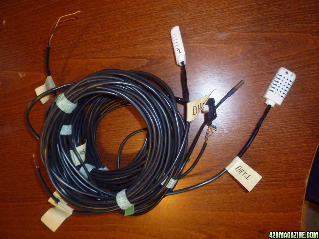
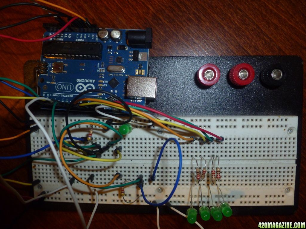
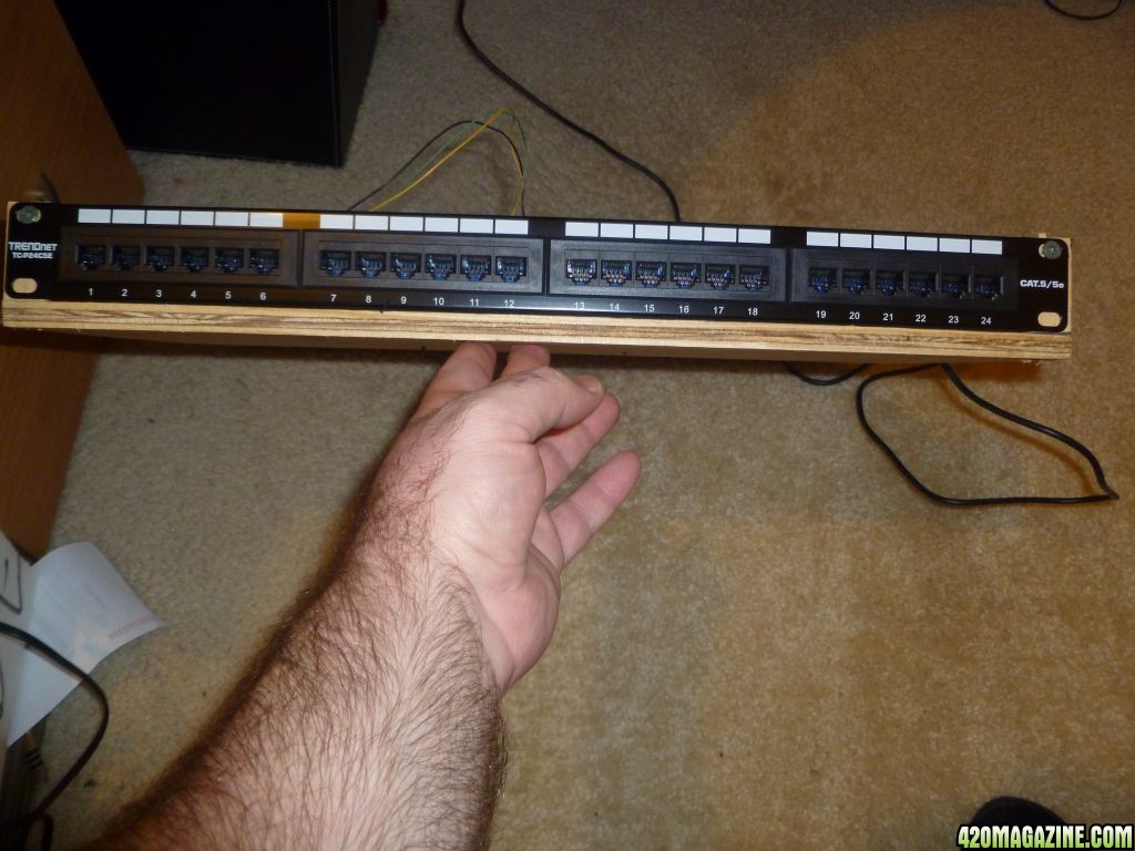
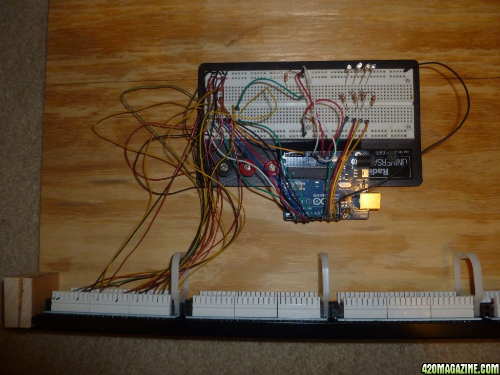
I added some programming to turn things on and off and on the breadboard I wired that to LEDs for some real world testing. I ordered a 24 port patch panel and I going to punch ends on to the sensors. I soldered each sensor to some 4 position solid core cable and heat shrunk the connections after testing and a little electrical tape. All code is on github.
Sensors:
Breadboard with simulation LEDs:
Sensors:
Breadboard with simulation LEDs:

")
I got my patch panel and I put ethernet ends on the sensor cables. I also got my patch panel and screwed everything to a piece of 1/4 ply. I punched down the wires and hooked it up to the arduino to run a test and it worked well.
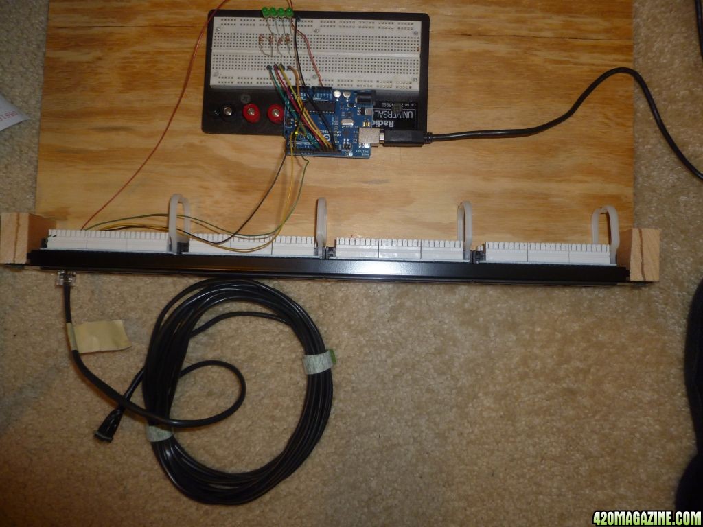
I also put a piece of velcro on the bottom of the arduino and the other side to my breadboard.
I also put a piece of velcro on the bottom of the arduino and the other side to my breadboard.
Wired everything and checked all the sensors work, planning on ordering a screw proto shield to finish it all off and take the breadboard out.
Which XBee should I choose? Also, how many pins does the Xbee use? I have found an Xbee shield but how many of the pins it plugs in to are in use by it?
Arduino XBee Shield
I guess the difference is Zigbee vs 802.15.4 protocol?? Can anyone chime in with experience?
Arduino XBee Shield
I guess the difference is Zigbee vs 802.15.4 protocol?? Can anyone chime in with experience?
I have a question about grounds - Does each ground belong to a certain group? Like the one on the digital side should be used to ground any digital pins (like my LEDs). The 3.3v, 5v then there are 2 grounds so is the top one for the 3.3 and the bottom for the 5? Are they all the same?!
PrairiePoet
Well-Known Member
I have a question about grounds - Does each ground belong to a certain group? Like the one on the digital side should be used to ground any digital pins (like my LEDs). The 3.3v, 5v then there are 2 grounds so is the top one for the 3.3 and the bottom for the 5? Are they all the same?!
On the Arduino all grounds are the same.
Thanks PP, do you have experience with the Xbee's? I want to use a higher power than I really need, even though the one mW is rated for 100m I would rather go with the 63mW, which antenna is better? I would like mesh networking in case some part of the grow is in another part of the house, or if someone has two tents (flower and veg, or flower and moms with clones). But dont both types support mesh? Or only the digimesh?
PrairiePoet
Well-Known Member
Thanks PP, do you have experience with the Xbee's? I want to use a higher power than I really need, even though the one mW is rated for 100m I would rather go with the 63mW, which antenna is better? I would like mesh networking in case some part of the grow is in another part of the house, or if someone has two tents (flower and veg, or flower and moms with clones). But don't both types support mesh? Or only the digimesh?
Sorry, I do not. Wanted a less expensive wireless than xBee. I'm using Wixel's right now and I'm getting about 50 feet, which covers my house.
How far do you need to go, and what will it need to go through? 100m range isn't much, and that I'm sure is BEST Conditions. But you can increase that with a decent antenna. You can build CANs that are directional and push out fairly far.
Mesh networking isn't easy. I would put that to the side and get everything else working. You are doing great, wish prods me to start posting where I'm at.....
Right now I'm working with Processing for the PC side. Graphing real time and keeping high, low and average with time stamps with multiple sensors coming from a remote Arduino. Got my PowerSwitch Tails in and will start coding those in as well. I guess I could post on my blog where I'm at. Try to do that tonight.
The adafruit page for the logger lists some tools for graphing on the PC side.
Data-Logger Shield for Arduino
When you say mesh is hard do you mean the code or the hardware? I read that you give them all the same passkey and they talk... I have no idea how you address them but I assume you use MAC address or something similar.
I would like the flexibility to put it anywhere on the property - so in the garage, basement or attic. I dont want to skimp $12 on the module and limit myself on what rooms or areas I put something in.
- Thread starter
- #199
OG13
New Member
Sorry I've been gone a while (up in big woods enjoying nature). Did the seed/sex boxes for a buddy, but have an issue with the relays......Still debugging. The fan circuit switching off occasionally causes the Arduino to reboot. They are on separate power supplies and output is isolated from input....makes no sense. Working on a mockup today.
Anyway, don't be surprised if you have some issues going from LEDs to actual output control.
The screw shields are handy for playing around off a breadboard.
Anyway, don't be surprised if you have some issues going from LEDs to actual output control.
The screw shields are handy for playing around off a breadboard.
Sorry I've been gone a while (up in big woods enjoying nature). Did the seed/sex boxes for a buddy, but have an issue with the relays......Still debugging. The fan circuit switching off occasionally causes the Arduino to reboot. They are on separate power supplies and output is isolated from input....makes no sense. Working on a mockup today.
Anyway, don't be surprised if you have some issues going from LEDs to actual output control.
The screw shields are handy for playing around off a breadboard.
You think I will have problems with the powerswitch tail?? If the pin is putting out 5v (hence lighting the LED) should that now turn on the device, and turn it off if it is at 0v?
The screw shield is my final stage, I figure I can screw down the data leds and then solder in any resistors and power connects, is there any reason to expect this will not be stable?
Similar threads
- Replies
- 2
- Views
- 2K
- Replies
- 28
- Views
- 4K