

BobbyZ
Well-Known Member
Do those cobs need the cones?
Nice job on that frame.


Nice job on that frame.
How To Use Progressive Web App aka PWA On 420 Magazine Forum
Note: This feature may not be available in some browsers.
I may have to take my reflectors off and re-run some of my numbers to see if I can see an increase too. Using reflectors is not all about PAR though, it has to do with directing the light downward for additional penetration, or at least that's how it works in the HID world... a good reflector hood could make all the difference there, helping not to waste so much light to the sides. These COBS though, are directing light in at least no more than 180°, so already they are better than an HID in that respect, and we may not actually need to focus that light. There is still so much to learn about LED!I have the reflectors, but will have to test the light with them on, and off of it. Timber Grow Lights no longer includes them, saying "Recent integrated sphere testing has shown a loss of almost 8-10% in PAR wattage using the reflectors vs not. Additionally, the light is able to be operated closer to the canopy with even PAR spread. "
I will put the reflector mounts on. I haven't done that yet to avoid damaging them since the catches drop below the frame.
I may have to take my reflectors off and re-run some of my numbers to see if I can see an increase too. Using reflectors is not all about PAR though, it has to do with directing the light downward for additional penetration, or at least that's how it works in the HID world... a good reflector hood could make all the difference there, helping not to waste so much light to the sides. These COBS though, are directing light in at least no more than 180°, so already they are better than an HID in that respect, and we may not actually need to focus that light. There is still so much to learn about LED!
I have been thinking about adding 2 more blue COBS to my array for veg and have been thinking a lot about not putting reflectors on these so that this light would spread out and mix with the other full spectrum lights while in veg.
I still think the reflectors serve a purpose. There may be bright and dark zones at various places under this array, but I don't think this matters to a plant sitting under it getting brighter light in one spot over another.
Consider too that at 6" you are really going to have some bright light there, but at 12 or 18" you are going to have multiple overlaps of varying distances and angles, all additive.
But again, being able to direct all of that light downward, not just 70% of it, by using a reflector, has got to help with penetration through the canopy. A good reflector is going to give you 98% of that output going downward, right where it needs to be. I am just not sure how much having even coverage is more important than forming these strong beams of canopy penetrating light or whether that even matters with these LEDs.

Nice job... But how does she grow?
Nice job... But how does she grow?
Path 4, light 1 furthest from your numbered paths numbers, seems to be getting more power? Am I reading this right? I just thought there would be more of a balance in those numbers.
I'd use the reflector cones, every number increased... Thanks for the numbers.
Thanks a lot. I'll make a start on my research there.Try @PurpleGunRack's threads Build Your Own LED Grow Light and DIY Test Build with Samsung Q-series strips.
GrowMau5 has a good series of videos on YouTube.
Feel free to ask. Any of us would be glad to help.
")
Check out Rapid LED, they have some content that may help. They sell a lot of GrowMau5 gear like his pucks which are essentially the exact same thing as a QB but in a different form factor. Likewise, a search of quantum board will turn up a lot of content too.Looks awesome! I'm looking into building something like this for my cabinet as I'm finding it tricky to find something that ideally suits my space. So thinking sod it I will build my own. Do you guys know any good links to read so I can get my head around the principles of building one of these and make the right part choices for my requirements? Any help would be much appreciated.
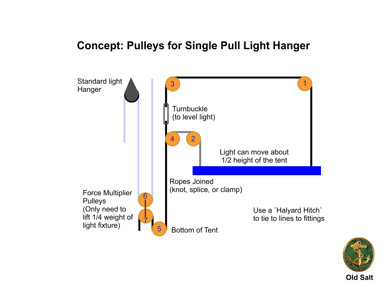
Impressive build OS, excited to see this thing in action.I've updated the concept drawing to show the force multiplier. Using it will limit the movement to about 1/2 the height of the tent.
Implementing the concept, this is what I've accomplished to date:
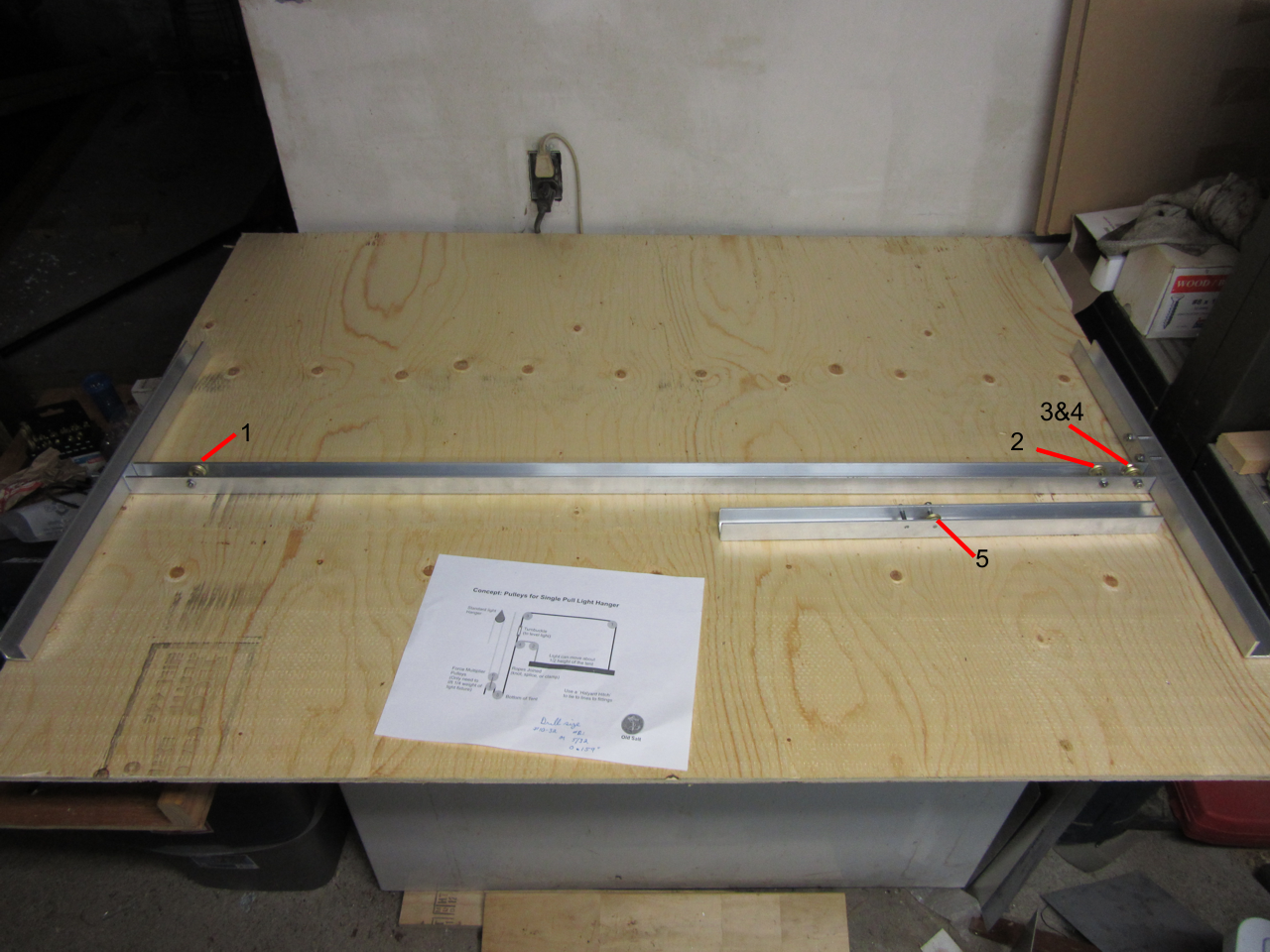
Overview of Light Hanger
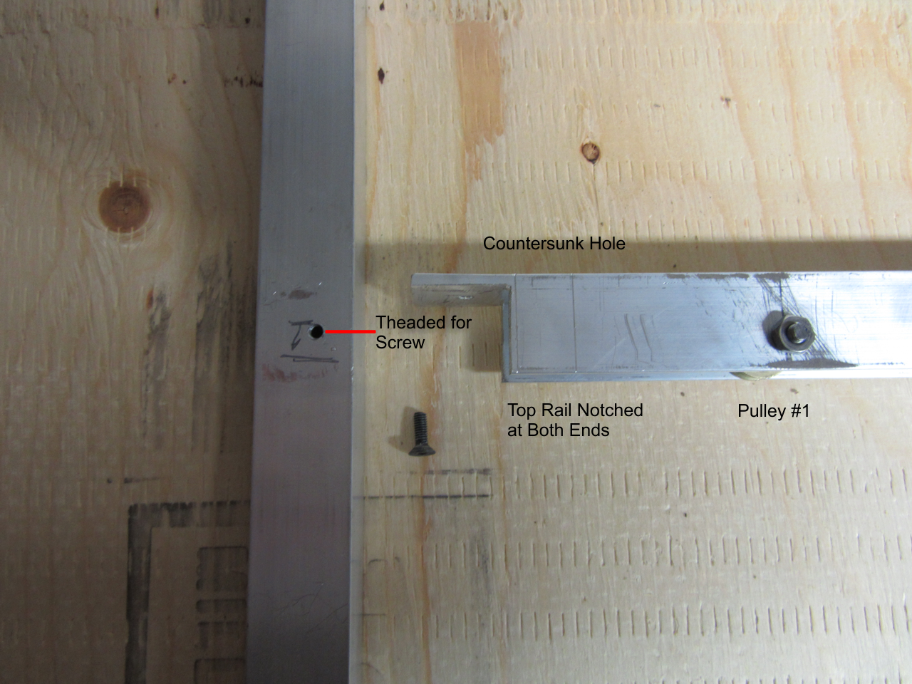
Left Side Details, Rail Connection
The top rail was notched so it rests on the side rails. I used countersunk screws to fasten it to the side rails. Rivets can also be used. Pan head screws or bolts with heads that protrude above the rail should be avoided. These can damage the roof of the tent if they come in contact with it. I intend to weld this connection later. The screw will work nicely in place of a clamp. Welding is not required, but as I have the equipment...
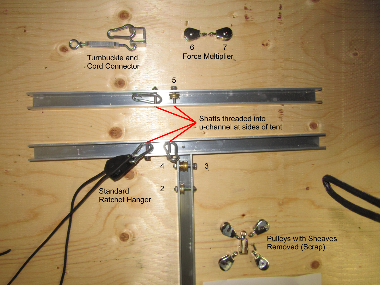
Right Side Details, Force Multiplier, and Cord Connectors
The cord connector is simply a piece of scrap u-channel, with three holes drilled in it. I'll pass a rope through the hole in the bottom, and use a stop knot to hold it in place.
The Force Multiplier pulleys can be tied together, but I'll use a piece of scrap metal to bolt them instead.
The shafts on the sheave (or wheel) donor pulleys can be drilled out, but I ground them down, and punched them out. The blocks and pins are now scrap. The sheaves in the rails will be braced with washers for stability. These needed to be drilled out a little for the shafts, I went 1/64" oversize for a 3/16" shaft. A piece of rope wrapped around them prevents damage when holding them in a vice for this operation.
The shafts were cut from 3/16" rod. The rod was held in a vice between two blocks of wood, then had seven threads cut on it. The shaft was then cut to length. Two nuts were locked together on the shaft, and four threads were cut on the other side for the top and bottom side rails. The shafts for the main center rail were cut a little longer, and have seven threads cut on each end. I used #10-32 taps and dies for threading. This means 4 threads are required to completely engage the walls of the u-channel.
Left to do is fabrication of the supports to hang the top assembly, and hold the bottom assembly down. I'll use sheet metal, and rivet them to the assemblies to avoid damaging the tent walls. I'll follow with a coat of paint, do the final assembly, and I'll call it done.