BirdieNumNum
Well-Known Member
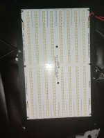
Just bought a used HLG QB288 V2 single Quantum Board.
I own several non HLG QBs
This one is running at about 30 to 50% brightness.
I suspect it has been mis wired - Can you help ?
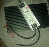
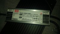
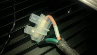
The two wires (Grey and Black) from the Dim cable coming from the meanwell HLG=150H-54B driver have been joined via electrical connector block. So no potentiometer or dim switch has been fitted ( I have one on order)
The mains power cable is fine.
The board is wired to the Meanwell driver power out cable as in the pics.
What is wrong with it ?
Thanks in advance....
I own several non HLG QBs
This one is running at about 30 to 50% brightness.
I suspect it has been mis wired - Can you help ?
The two wires (Grey and Black) from the Dim cable coming from the meanwell HLG=150H-54B driver have been joined via electrical connector block. So no potentiometer or dim switch has been fitted ( I have one on order)
The mains power cable is fine.
The board is wired to the Meanwell driver power out cable as in the pics.
What is wrong with it ?
Thanks in advance....